Synchronous Design Techniques
Synchronous Design Techniques . Objectives. After completing this module, you will be able to: Use the hierarchy effectively Increase the circuit reliability and performance by applying synchronous design techniques. Outline. Hierarchical Design Synchronous Design for Xilinx FPGAs Summary.


Synchronous Design Techniques
E N D
Presentation Transcript
Synchronous Design Techniques This material exempt per Department of Commerce license exception TSU
Objectives After completing this module, you will be able to: • Use the hierarchy effectively • Increase the circuit reliability and performance by applying synchronous design techniques
Outline • Hierarchical Design • Synchronous Design for Xilinx FPGAs • Summary
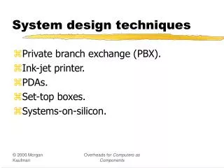
Hierarchical Design Using hierarchy leads to greater design readability, reuse, and debug Top Level of Design Infer or instantiate I/O here One way to divide your design into hierarchical blocks is by logic type State Machines Datapaths One-hot Pipelining Binary Muxing/De-Muxing Enumerated Arithmetic Counters Building Blocks Adders/Subtractors Standard Widths Bit Shifters Pipeline RAMs Accumulators Specific Functions RAM Other IP/Cores CoreGen FIFOs Parametizable functions RAM FIR Filters Technology-Specific Functions
Benefits of Using Hierarchy • Design readability • Easier to understand the design functionality and data flow • Easier to debug • Easy to reuse parts of a design
Design Readability Tips • Choose hierarchical blocks that have the following: • Logical data flow between blocks • Minimum of routing between blocks • Choose descriptive labels for blocks and signals • Keep clock domains separated • Makes the interaction between clocks very clear • Keep the length of each source file manageable • Easier to read, synthesize, and debug
Design Reuse Tips • Build a set of blocks that are available to all designers • Register banks • FIFOs • Other standard functions • Custom functions commonly used in your applications • Name blocks by function and target Xilinx family • Easy to locate the block you want • Example: REG_4X8_S3 (bank of four 8-bit registers targeting Spartan-3) • Store in a directory that is separate from the Xilinx tools • Prevents accidental deletion when updating tools
Outline • Hierarchical Design • Synchronous Design for Xilinx FPGAs • Summary
Why Synchronous Design? • Synchronous circuits are more reliable • Events are triggered by clock edges that occur at well-defined intervals • Outputs from one logic stage have a full clock cycle to propagate to the next stage • Skew between data arrival times is tolerated within the same clock period • Asynchronous circuits are less reliable • Delay may need to be a specific amount (for example, 12 ns) • Multiple delays may need to hold a specific relationship (for example, DATA arrives 5 ns before SELECT)
Asynchronous DesignCase Studies • The design I created two years ago no longer works. What did Xilinx change in their FPGAs? • SRAM process improvements and geometry shrinks increase speed • Normal variations between wafer lots • My design passes a timing simulation test but fails in-circuit. Is the timing simulation accurate? YES • Timing simulation uses worst-case delays • Actual board-level conditions are usually better
D D Q_A 12.5 A B C Q_B D 3 cycles Clock Q_A Q_B Q_C 2 cycles A & C Clock B Clock 3.0 3.1 3.0 3.3 3.1 Q_A Clock skewed version Expected operation Q_B Q_C Clock Skew • This shift register will not work because of clock skew! INPUT Q_C CLOCK
Use Global Buffers to Reduce Clock Skew • Global buffers are connected to dedicated routing • This routing network is balanced to minimize skew • All Xilinx FPGAs have global buffers • Virtex™-II and Virtex-II Pro devices have sixteen BUFGMUXes • Spartan™-3 devices have eight BUFGMUXes • Virtex-4 devices have 32 BUFGCTRLs • You can always use a BUFG symbol, and the software will choose an appropriate buffer type • All major synthesis tools can infer global buffers onto clock signals that come from off-chip
Using Global Lines • Most synthesis tools will automatically infer a BUFG on clocks • Clock signals must come from a top-level port • Internally generated clocks are not automatically placed on a BUFG • Sample instantiation of BUFGMUX (Verilog) BUFGMUX U_BUFGMUX (.I0( ), // insert clock input used when select(S) is Low .I1( ), // insert clock input used when select(S) is High .S( ), // insert Mux-Select input .O( ) // insert clock output ); • Note: These templates, and templates for other BUFGMUX configurations, are available in the ISE™ language templates
Traditional Clock Divider • Introduces clock skew between CLK1 and CLK2 • Uses an extra BUFG to reduce skew on CLK2 D Q CLK2 D Q BUFG CLK1 BUFG
Recommended Clock Divider • No clock skew between flip-flops D Q CLK2_CE CE D Q CLK1 BUFG
Avoid Clock Glitches • Because flip-flops in today’s FPGAs are very fast, they can respond to very narrow clock pulses • Never source a clock signal from combinatorial logic • Also known as “gating the clock” MSB 0111 1000 transition can become 0111 1111 1000 due to faster MSB MSB Shorter routing FF LSB Glitch may occur here Binary Counter
Avoid Clock Glitches • This circuit creates the same function, but it creates the function without glitches on the clock D INPUT Q3 D Q2 Q CE Q1 Q0 FF CLOCK Counter
Coding Clock Enables May infer extra logic if you do not follow the correct order of precedence • If ENABLE is not a top-level port, write the code for ENABLE in another process • Makes the code more readable • Helps the synthesis tools create better netlists • Control signal precedence: Reset, Set, Enable • Use this order in your code VHDL FF_AR_CE: process(CLK) begin if (CLK’event and CLK = ‘1’) then if (ENABLE = ‘1’) then Q <= D_IN; end if; end if; end process Verilog always @(posedge CLOCK) if (ENABLE) Q = D_IN;
Avoid Set/Reset Glitches • Glitches on asynchronous set and asynchronous reset inputs can lead to incorrect circuit behavior INPUT Q D Asynchronous Reset FF Binary Counter CLR RESET Q[x] Q[0] CLOCK A glitch could occur duringthe 01 10 transition
Avoid Set/Reset Glitches • Convert to synchronous set and synchronous reset when possible INPUT Q D Synchronous Reset FF Counter R RESET Q[x] Q[0] CLOCK Prevent the transitionof 01 10 from occurring
Coding Synchronous Flip-Flops • Asynchronous Reset always @(posedge CLOCK or posedge RESET) if (RESET) Q = 0; else Q = D_IN; • Synchronous Reset always @(posedge CLOCK) if (RESET) Q = 0; else Q = D_IN;
Outline • Hierarchical Design • Synchronous Design for Xilinx FPGAs • Summary
Review Questions • List two benefits of hierarchical design • Why should you use global buffers for your clock signals? • What is an alternative to gating a clock?
Answers • List two benefits of hierarchical design • Design readability • Design reuse • Why should you use global buffers for your clock signals? • To reduce clock skew • What is an alternative to gating a clock? • Use a clock enable
Summary • Proper use of the hierarchy aids design readability and debug • Synchronous designs are more reliable than asynchronous designs • FPGA design tips • Global clock buffers and DLLs eliminate skew • Avoid glitches on clocks, asynchronous sets, and asynchronous resets
Where Can I Learn More? • Application notes on www.xilinx.com Documentation Application Notes • Software documentation on www.xilinx.com Documentation Software Manuals • Development System Reference Guide, Chapter 2: Design Flow, FPGA Design Techniques section • Libraries Guide • Documentation for your synthesis tool