Download
1 / 60
600 likes | 818 Vues
Group 1. MAHST Mini At-Home Solar Thermal Power Generation. Homa Amini Manesh Aaron Birencwaig Nitesh Champaneri Jonathan Wise. Motivation. Recent Catastrophe With Non-Green Energy Sources:

E N D
Group 1 MAHST Mini At-Home Solar Thermal Power Generation Homa Amini Manesh Aaron Birencwaig Nitesh Champaneri Jonathan Wise
Motivation • Recent Catastrophe With Non-Green Energy Sources: • 13,000 death each year attributed to power plant pollution according to the Clean Air Task Force study in 2000 and 2004. • Upper Big Branch Mine disaster • Japan’s Recent Nuclear Meltdown • Gulf Oil Spill • Problems With Traditional Power Generation: • High Cost • Limited Supply of Fossil Fuel • Lack of Economic Independence
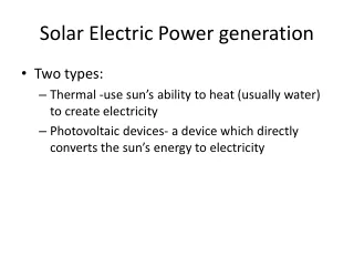
Solution To prevent these problems, making use of a clean renewable energy source is ideal. Our solution is to combine both solar thermal and solar photovoltaic panel technologies into a single power generating unit known as MAHST. MAHST stands for Mini At-Home Solar Thermal power generation.
Goals and Objectives • MAHST Offers: • Clean and Renewable Source of Energy • Affordable for Average Household • User Friendly • Power Grid Independence • Portability • Efficiency
Specification • Stirling engine generates 10 watts peak power at 12 volts under ideal conditions • PV panel produces peak power outputs of 30 watts at 24 volts • Total power of 40 watts maximum under ideal conditions • Two 12 V DC lead acid Absorbent Glass Mat batteries • 5 V, 600mA switching regulator powering two microcontrollers • 12V, 700mA DC/DC switching regulator powering the tracking system motors • The monitoring system displays: • Temperature of the battery to within ±1°C of accuracy • Power being generated within ±2 watts of the actual value • Voltage of the battery within ±0.5 volts of the actual value • 5 V DC, 700mA USB power outlet • 12 V DC power outlet
Stirling Engine • Invented in 1816 • Advantages • One of the cleanest and most efficient heat engines • Runs on any source of heat • Its working fluids may consist of air, helium, or hydrogen • Safe because of its closed system • Different types of engines for different applications The Stirling Engine of 1816
Types • Alpha-α Beta-β Gamma-γ Stirling Engine
Stirling Engine • Mechanism • Hot and cold heat exchanger • Hot heat exchanger is in the direct contact of an external • heat source • Four thermodynamic processes • Movement of the working fluids between the hot and cold • heat exchangers • Ideal Gas Law: PV=nRT
Stirling Engine • Characteristics • Made in New Zealand • Beta-βType • Driving a small DC generator • Specifications • 2 volts / 100 rpm • 10-15 volts • Output Power:10 Watts • Thickness of Hot Cap: 0.0039 - 0.0059 inches • Required Heat : 932-1112°F • Cost: $ 315.00
Solar Panel • Model: GSE 30 Watts • Advantages • Thin film Copper Indium Gallium diSelenide (CIGS) • Higher Conversion Efficiency • No light induced degradation • Designed for charging 12 and 24 volt lead acid batteries • 25 years Warranty • Lightweight • Easy to install • Includes a junction box with a by pass diode • FREE!!!
Solar Panel • Specifications • Model: GSE 30Watts • Peak Power Voltage: 17.5V • Peak Power Current: 1.7A • VOC : 25V • ISC : 2.2A • Length x Width : 24.4 x 25(inches) • Weight : 11 lbs • Cost (if we would of purchase one): $289
Reflective Dish • Provides the heat source for the Stirling cycle motor • Reflects light into a single focal point amplifying the heat • Utilizes mirrors or Mylar to reflect heat energy from the sun
Reflective Dish Construction • The reflective material must imitate the dish’s parabolic form • Glass or plastic silver backed mirrors seem to generate the most intense focal point • The wider the focal point, the less heat can be generated by the dish
Surface Area of a Parabolic Dish • The surface area must be known for mirroring purposes and to see if sufficient heat can be generated • The general equation of a parabola is when a isand f is the focal point
Surface Area of a Parabolic Dish • The focal point can be found with the equation • = 12 inches where D is the diameter and d is the depth of the dish • The surface area of any parabolic dish can now be found with the equation • = 479.5 in^2
Tracking System • What is a solar tracking system? • A tracking system is a setup that will enable the • user to follow the sun across the sky • Purpose of using a tracking system: • 1. Maximize the amount of energy that is capable of • being produced by the solar cells • 2. Provide solar cells with more direct sunlight. • 3. Allow cells to receive more hours of sunlight. • 4. Permits Stirling engine to run for more hours a day • 5. Enables the dish to create a higher overall • heat
Timed Tracking System • Advantages • Less power consumed by turning engines • Better tracking of the sun with cloud blockage • Returns to starting position after sunset • Preprogrammed rotation times
Tracking System With Light Sensors • Photo resistors or photoconductors decrease resistance with increasing incident light intensity . • Made from high resistance semiconductor material.
Tracking System With Light Sensors • Voltage differences can be sensed by the microprocessor as the resistance decreases in one of the resistors when two resistors are in series and one is fixed. • The microcontroller will be programmed to instruct the motor to turn towards the resistor with the least resistance allowing for the tracking system to point towards the brightest light source.
Timed Tracking System With Fine Tuning Resistors • A timed tracking system will only allow for the motors to turn at proper intervals to nearly the correct location in which the sun will be located, then fine tuning can be used with photo resistors in order to point directly at the sun with the most accuracy.
Tracking System (Two Degrees of Freedom) • Increases the amount of energy created by solar cells from 20-60% compared to cellswithout a tracking system • Allows for more parallel rays of light to be captured than a system with a single degree of freedom. 1 Degree of Freedom 2 Degrees of Freedom
Motors for Tracking • Low revolution high torque motor • Geared motor • 12V motor .020 Amperes without load • 4 Revolutions a minute • Part# PP GF30 Approximately $5.00, used in the automotive industry
Microcontroller for Tracking System • PIC 16F690 Microcontroller • 8MHz with 7Kb of memory • -40 º F – 257 º F • Rated for forty years • 20-Pin Flash-Based • Operating voltage 2.0-5.5V • Low power and power saving options
MAHST Monitoring System Goals and Objectives • Display power generated • Display battery charge state • Display the temperature inside the MAHST unit
Atmel ATmega328p • 28 pin DIP package • 1.8v – 5.5v operating range • 32kb of flash memory • 23 programmable I/O lines • 6 ADC channels • 10 bit ADC • Boot loader support • Compatible with Arduino UNO • $4.30
Arduino IDE and UNO Board • Programmable in C • Extensive list of hardware libraries • Simple layout and easy to use • No code size limitations • Large support community • Open source/free • UNO board with ATmega328p • $26.95
Allegro ACS712 ELCTR-05B-T Current Sensor • Senses both AC and DC currents • Measures up to ±5 amps • 4.5 to 5.5 V supply voltage • -40 to +85°C operating range • ±1.5% error at TA = 25° • $4.52 Output voltage is a linear function of input current V = (1/5)I+2.5
TMP37 Temperature Sensor • Normal range of 5 - 100°C • Normal accuracy ±1°C • Extended range >125°C • Extended accuracy ±2°C • Supply voltage of 2.7 – 5.5V • $1.68 Output voltage is a linear function of temperature V = 0.02T
Character Display • Displays 20X4 characters • Based on Hitachi HD44780 • Compatible with Arduino • $19.95
Voltage Sensing • Need voltage scaled down to the µController’s 5V ADC range • Power dissipation should be as small as possible • Need output impedance of sensor to be less than 10kΩ • Op-amp allows for the output impedance to be lower than 10kΩ • R1 = 200kΩ, R2 = 100kΩ for 15V input max • R1 = 400kΩ, R2 = 100kΩ for 25v input max • Resistor ratios allow the max input current to be 50µA
Monitoring System Program Flow Two variables SEL and NAV correspond to the selection and navigation buttons of the user interface. They allow the user to navigate through the MAHST monitoring system menu.
Monitoring System Functions • float TMP37(int AR); Automatically converts the analog reading into a Fahrenheit temperature using the linear equation T= 50V*1.8+32 • float VFT(int AR); Allows for the analog voltage readings to be converted to the sensed voltage using the scale factor of the resistor ratio • float VTF(int AR); Converts voltage readings for the 25V max sensor to a float value. • float Current(int AR); Returns a float with the value of the current to two decimal places. And makes corrections for nonlinearities. I = (V-2.5)*5
Charge State Functions float BCSA(void); This function estimates the charge state of the battery by using the parameters listed below. The function will display a “N/A” charge state when the generators are not producing energy, and “Charging” when the sources are producing. Once the conditions in the function are satisfied, the “charge” variable is set to 64800 coulombs. • Panel voltage • Battery charging voltage • Current being generated by the sources • Net current entering the battery float DCSA(void); This function determines the decreasing charge state of the battery. It runs in the background of the monitoring system, and measures the current leaving the battery each second. Then the function either decreases or increases the “charge” variable based on the amps entering or leaving the battery per second.
Battery Types • Starting • Used for starting and running the engine • Provides large amounts of current • 30-150 deep cycle life • They will last more than thousand normal cycles • Deep Cycle • Could be discharged up to 80% time after time • Has less surface area thus less instant power • Best to keep them at 50% discharge cycle
Battery Material • Nickel-Cadmium • Nickel-metal hydride • Lithium-ion • Lithium-ion polymer • Lead-acid • Mature technology • Better storage capacity • Cost effective • Self discharge rate about 40% a year • No memory effect • Saves natural resources since its fully recyclable • If used correctly they can last 5-8 years
AGM Advantages Over Gelled & Flooded Batteries • Cannot spill, even if broken • Non-hazardous (low shipping cost) • Immune to freezing damage • Temperature stays low even during heavy charge and discharge current • Sit in storage for much longer period • Withstand shock and vibration better than any standard battery • No maintenance • Completely sealed against fumes
Battery Characteristics • Brand – Power Sonic • Model – 12180 B • Nominal Voltage – 12 volts (6 cells) • Nominal Capacity – 18Ah/20h = 900mA • Weight – 12.6 lbs. (5.72Kg) • Internal resistance – 14 milliohms • Max discharge current – 54 A • Operating Temperature • Charge – -4F to 122F • Discharge – -40F to 140F
Battery Dimensions • Length – 7.13 inches • Width – 3.00 inches • Height – 6.59 inches
Voltage & Charge Regulators • 6 Voltage Regulators • Tracking system microcontroller – 5V, 600mA • Monitoring system microcontroller – 8V, 1.5A • Tracking system motors – 12V, 700mA • Solar panel – SEPIC converter – 14.5V, 2.2A • Powering NE555 for charge controller – 5V, 1.5A • USB 2.0 charger output – 5V, 600mA • Charge Controller
Voltage Regulator (Powering Tracking System Microcontroller) • LM2676S -5.0 • Switcher High efficiency (94%) Step-down Voltage regulator • 2% maximum output tolerance • Junction temperature range -40 to +125 C
Voltage Regulator Schematics (Powering Tracking System Microcontroller)