Scan tool diagnosis
OBD. OBD stands for On Board DiagnosticsGM coined the term to describe the self-diagnostic feature included in their computerized engine controlsAll manufacturers gradually accepted and integrated OBD in their own waysFrom 1988-1994 California was the only place to require OBD standards. OBD history.

Scan tool diagnosis
E N D
Presentation Transcript
1. Scan tool diagnosis OBD 0, 1, AND 2
2. OBD OBD stands for On Board Diagnostics
GM coined the term to describe the self-diagnostic feature included in their computerized engine controls
All manufacturers gradually accepted and integrated OBD in their own ways
From 1988-1994 California was the only place to require OBD standards
3. OBD history
4. OBD history 1975: Datsun 280Z - On-board computers begin appearing on consumer vehicles, largely motivated by their need for real-time tuning of fuel injection systems. Simple OBD implementations appear, though there is no standardization in what is monitored or how it is reported.
5. OBD history 1980: General Motors implements a proprietary interface and protocol for testing of the engine control module (ECM) on the vehicle assembly line. The 'assembly line diagnostic link' (ALDL) protocol communicates at 160 baud with Pulse-width modulation (PWM) signaling and monitors very few vehicle systems.
6. OBD history Implemented on California vehicles for the 1980 model year, and the rest of the United States in 1981, the ALDL was not intended for use outside the factory. The only available function for the owner is "Blinky Codes". By connecting pins A and B (with ignition key ON and engine OFF), the 'Check Engine Light' (CEL) blinks out a two-digit number that corresponds to a specific error condition.
7. OBD history Cadillac (gasoline) fuel-injected vehicles, however, are equipped with actual on-board diagnostics, providing trouble codes, actuator tests and sensor data through the new digital Electronic Climate Control display. Holding down 'Off' and 'Warmer' for several seconds activates the diagnostic mode without need for an external scan-tool.
8. OBD history 1987: The California Air Resources Board (CARB) requires that all new vehicles sold in California starting in manufacturer's year 1988 (MY1988) have some basic OBD capability. These requirements are generally referred to as "OBD-I", though this name is not applied until the introduction of OBD-II. The data link connector and its position are not standardized, nor is the data protocol.
9. OBD history 1988: The Society of Automotive Engineers (SAE) recommends a standardized diagnostic connector and set of diagnostic test signals.
This is the start of manufacturers incorporating OBD functionality into more and more cars
10. OBD history 1994: Motivated by a desire for a state-wide emissions testing program, the CARB issues the OBD-II specification and mandates that it be adopted for all cars sold in California starting in model year 1996 (see CCR Title 13 Section 1968.1 and 40 CFR Part 86 Section 86.094). The DTCs and connector suggested by the SAE are incorporated into this specification.
11. OBD history 1996: The OBD-II specification is made mandatory for all cars sold in the United States.
2001: The European Union makes EOBD mandatory for all petrol vehicles sold in the European Union, starting in MY2001.
2008: All cars sold in the United States are required to use the ISO 15765-4 [2] signaling standard (a variant of the Controller Area Network (CAN) bus).
12. OBD history OBD 1 included the ability to recognize a fault in the engine system, and store a �trouble code�
It also lights a �check engine� light to indicate to the driver that something is wrong with the vehicle
Check engine light may be called a fault indicator or a malfunction indicator light - MIL
13. OBD history
14. OBD history Unfortunately, the California standards left a lot of room for interpretation by the auto manufacturers
Every manufacturer had their own version of OBD 1 � each version had their own trouble codes and diagnostic procedures
Each manufacturer also had their own �scan tool� and diagnostic connector � none were interchangeable between makes
15. OBD history
16. OBD history The early OBD systems were able to recognize failures in several major systems � however, without a major failure, there were no provisions for just �out of spec� systems
If a component was simply out of adjustment or not quite failing, the system could not detect it
The vehicle could show no faults � but still be running badly
17. OBD history OBD 2 was invented to alleviate OBD 1�s flaws
OBD 2�s main objective is emissions related
The aim is to make sure every vehicle is functioning properly for the life of that vehicle
18. OBD history
19. OBD history OBD 2 accomplishes total emissions monitoring by:
Keeping tabs on emission performance directly � by way of emissions monitors
Standardizing all OBD 2 systems � universal fault codes, data connectors and diagnostic procedures � this makes it easier for a technician to work on different makes of cars
20. OBD OBD 1 was required to monitor 3 systems:
EGR systems
Fuel Metering
Major sensor inputs � cam, throttle, etc.
21. OBD OBD 2 monitors:
Catalyst efficiency
Engine misfire
Enhanced EGR monitor
Enhanced sensor inputs and outputs
Enhanced fuel system monitor
Enhanced heated O2 monitor
Evaporative emission system integrity
Secondary AIR system function
CFC�s in the air conditioning system (though CFC�s are not used post 1996)
22. Computer system overview Every onboard computer has 3 segments:
Inputs, Processor, Outputs
These join together to form a �closed loop� to sense, analyze and adjust engine performance
The inputs sense the conditions, the processor interprets and controls, and the outputs make the adjustments that the processor requests
23. Computer inputs Computer inputs are:
Variable resistor (air temperature)
Variable voltage (O2 sensor)
AC frequency (knock sensor)
DC frequency
Switch
24. Computer inputs The onboard computer measures inputs in only 2 ways � voltage and frequency
Frequency is measured in Hertz (Hz) or cycles per second � the computer counts them
The computer cannot use raw voltage � it must be transformed into a digital signal for the computer to use
25. Computer inputs
26. Computers
27. Computer processing The computer consists of :
A microprocessor
Read Only Memory (ROM)
Programmable ROM (PROM)
Random Access Memory (RAM)
28. Computers
29. Processor The processor receives inputs and develops output signals
Makes decisions based on information stored in the ROM and PROM
The ROM is the �generic� information
The PROM is vehicle specific info for the vehicle
30. Processor RAM is the computer�s short term memory
Trouble codes, fuel trim data, and any on-road adjustments the computer makes are stored in the RAM
RAM can be changed or erased based on the computer
PROM can be reprogrammed only with manufacturer tools (a set number of times)
ROM cannot be altered
31. Computers
32. Computer outputs Computer outputs are:
Solenoids (fuel injectors)
Lights (MIL or warning lights)
Motors (IAC
Relays
Transistors (igniters)
33. Computer outputs Every output starts as a digital signal
The signal must be converted from digital to a voltage
The digital signal goes from the computer to a transistor that turns it into a voltage
The transistor can be integral to the computer, or external like an ignition module
34. OBD 2 OBD 2 in principle sounds great:
All makes and model cars have set DTC�s
All OBD controlled parts have the same names for all makes
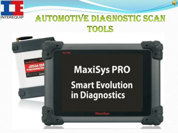
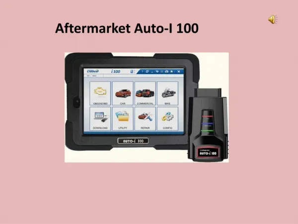
Every make will use the same diagnostic plug
Every make will have the same scan-ability � 1 scanner can scan OBD codes on all makes
A P0710 code on an Audi will be the same code as on a GM, Ford, Chrysler, etc.
35. Data link connector The data link connector or DLC is the plug that is located on the vehicle that an OBD scan tool is plugged into
The plug is regulated to be �between the steering column and the center of the vehicle, and visible from the driver seat� on all vehicles
Usually under the steering column close to the driver door
36. DLC
37. DLC
38. DLC All DLC connectors are a 16 pin connector
39. Terminology Diagnostic, or Monitor � tests by the PCM to check all OBD systems � failure by any monitor turns the MIL light on
Enabling criteria � sensor inputs during specified driving conditions � must be received by the PCM before the monitor can be run (engine temp, speed, load, gear, etc.)
Warm up cycle � the time it takes the engine to warm from ambient to 160*F
40. Terminology Drive cycle � a set of driving conditions that run all monitors � after all monitors are run, then the vehicle sets �readiness� for inspection/maintenance (IM) flags � all tests have passed when readiness is set
Passive test � a test that checks the performance of a vehicle system during normal operation
41. Terminology Active test � a test that forces a monitor to run or a component to operate � a scan tool is usually used to run the test
Failure record � stored DTC memory in the PCM � stored in order that they occurred, usually with some freeze data to indicate conditions � they must be repaired in the order of 1st to last
42. Terminology Trip � a key on, engine running, key off cycle in which all the diagnostic criteria to run a specific monitor is met
Freeze frame data � serial data values that are stored the instant a DTC is set � sped, temp, load, conditions, etc.
Inspection/maintenance (IM) ready status � called Readiness � all monitors have run and passed
43. Terminology Closed loop operation � occurs when the PCM processes electrical inputs from all sensors to control the fuel delivery and all systems associated with the running engine � the engine is getting data from the sensors, not a base PCM map
Open loop � vehicle is running and warming up based on PCM maps � no sensor input is recognized by the PCM until engine warms and closed loop occurs
44. Closed loop
45. OBD trouble codes A DTC is displayed as an alphanumeric designator followed by a 3 digit number
These codes are displayed on the scanner
All OBD codes are now standardized, so a P0411 for a Ford will be the same for a VW, Chrysler, BMW, etc
46. DTC
47. OBD trouble codes Codes fall into 4 groups:
Body codes : B0, B1, B2, B3
Chassis codes : C0, C1, C2, C3
Powertrain codes : P0, P1, P2, P3, P4
Network codes : U0, U1, U2, U3
48. P codes Engine performance DTC�s are found in the P codes
If the code is P0xxx � it is a generic, standardized SAE code � the same code for all autos
If the code is a P1xxx � it is a manufacturer specific code that needs a manufacturer specific diagnostic procedure � these codes are not standardized
49. P codes The second number of a P code, as in P01xx, designates the affected systems
1 � fuel and air metering
2 � fuel injectors
3 � ignition or misfire systems
4 � auxiliary emission controls
5 � vehicle speed control and idle
6 � computer output circuits
7 � transmission
8 � transmission
50. P codes The last 2 numbers, as in P0137, is the specific fault
So, P0137 is a generic engine code, affecting the fuel metering, and indicates the number 2 heated oxygen sensor on cylinder bank 1 is producing a low voltage
The number 1 cylinder bank always contains number 1 cylinder
51. P codes
52. Diagnostic flow chart A diagnostic flowchart is a chart with a procedure to diagnose a specific DTC
Each DTC has a corresponding flow chart in the factory repair manual
It provides a step-by-step procedure to diagnose the DTC and find its cause
53. Diagnostic flow chart
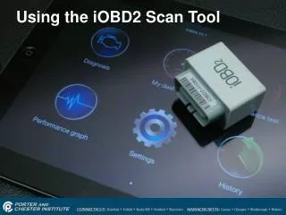
54. Scan tool Next class, we will use the scan tools in vehicles
I will show you how to hook them up, turn them on and look at DTC�s