Download
1 / 23
230 likes | 544 Vues
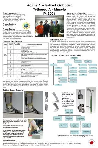
Multi S urface Sensing Ankle Foot Orthotic for Foot Drop. Christopher R. Sullivan Mechanical Engineering Student Research & innovation Symposium August 12 th , 2011 Advisor: Elizabeth A. DeBartolo, Ph.D. Gait Cycle and Foot Drop. Stance. Swing. Swing. Initial Double-Limb Support.

E N D
Multi Surface Sensing Ankle Foot Orthotic for Foot Drop Christopher R. Sullivan Mechanical Engineering Student Research & innovation Symposium August 12th, 2011 Advisor: Elizabeth A. DeBartolo, Ph.D.
Gait Cycle and Foot Drop Stance Swing Swing Initial Double-Limb Support Terminal Swing Second Double-Limb Support Mid-Swing Single-Limb Stance Initial Swing Periods Terminal Swing Initial Swing Mid-Swing Periods Foot Strike Opposite Toe-Off Opposite Foot Strike Tibia Vertical Foot Clearance Foot Strike Toe-Off Toe-Off % of Cycle Foot Crash Mid Trip Fallen 62% 0% 100% % of Cycle 62% 100% Image Source: http://sports.jrank.org/article_images/sports.jrank.org/dorsiflexion.1.jpg
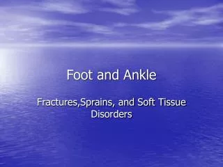
What is an Ankle Foot Orthotic? • Replace lost ankle functionality • Foot drop • Correct brace for the correct problem Dynamic Walk Jointed Brace Solid Brace Image Source: http://www.mobilelimbandbrace.com/images/Articulating_AFO_Overlap.gif http://www.spsco.com/assets/images/dynamic-walk-single-side-2_large.jpg http://proactiveasia.com/web_image/orthotics/Trulife%20semi-solid-afo_web.gif
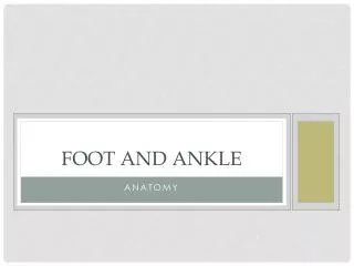
Project Goal • Create an Ankle Foot Orthotic (AFO) that adapts to differing terrain to provide the correct amount of support • Todays talk • Stakeholder interviews • Needs assessment • Preliminary design • Preliminary analysis Image Source: http://transit-safety.volpe.dot.gov/publications/safety/pedestrian/html/images/dot-tsc-umta-84-36_p0009a.gif
Stakeholder Interviews • Interviewed Clients, Clinicians,and ProsthetistOrthotist • Major takeaways • Foot drop has many other compound symptoms • Pros • Allow clients to walk • Cons • weight/bulk of the AFO • Instability on ramps and stairs • AFO user’s needs can differ widely Image Source: http://www.humanresourcesdegree.net/images/stories/School%20Logos%20-%20Masters/NazarethCollege.jpg http://www.workforcediversitynetwork.com/images/logos/RGHS_stacked_150.jpg http://www.rochesterorthopedic.com/
Defining the Target Clients • They should be able to supply feedback • Would not be a candidate for a commercially available AFO • Must use a jointed brace
Customer Needs • Fits into a shoe • Ease of access • Adjustability • Light weight • Portable • Inexpensive • Able to be used on both sides of the body • Safety • Durability/fatigue life • Biocompatible surface • Able to be cleaned/sterilized • Functionality • Provide appropriate support for the foot at the appropriate time • Stairs • Ramp • Level surface
Functional Block Diagram Multi Surface Sensing Ankle Foot Orthotic Micro-Controller Ground Identification Sensor If Ground Profile Level Ground Range of Motion Stairs or Ramp Position Power Actuator
Proposed Design • Attaches to the back of existing AFO • Linear actuator shifts carriage to either side • Carriage holds two individually adjustable backstops • The actuator doesn’t have to support the foot • Infrared range finder • Detect terrain
θ3 Moment about the Ankle During Swing m2 m3 θ2 θ4 m4 m1 m5 θ5 x θ1
Next Steps • Device attachment to brace • Find Ramp Gait Data • Select and test Range Finder • Select and test Actuator • Define algorithm for determining floor surface • Model Design • Build and test
Acknowledgments Funding was supplied by the RGHS RIT alliance Seed fund Rochester General Hospital Richard L Barbano, MD, Ph.D., FAAN Advisor Elizabeth A. DeBartolo, Ph.D. Thesis Committee Mario Gomes, Ph.D. Kathleen Lamkin-Kennard, Ph.D. Nazareth College Physical Therapy Clinic J.J. Mowder-Tinney PT, PhD, NCS Rochester Orthopedic Labs Shawn Biehler, CPO
LaGrange's Method LaGrangian operator LaGrangian force Link kinetic energy Link potential energy Resistive Energy
Solution Combinations Design 1 Variable peek Rod Design 3 Variable peek Rod Geo Fit
IR Range Finder • Feasibility • Look into expected data 1.5” 4” 8” 12” 24” 31.5” 40” 59.5” 216.5” Source: http://www.technologicalarts.com/myfiles/data/gp2d120.pdf Figure 9. Sharp IR sensors Minimum Range Maximum Range Figure 10. Sharp IR sensors Distance Illustration
Issues with Design • It adds weight • Make the Brace Lighter • Attaching to the back of an existing AFO • Adhesive • Vacuum • Use existing backstop • Velcro • Actuation • Piezoelectric Linear actuator • Knowing the Ground • Accelerometer • IR Range Finder
Accelerometers • Require a lot of data analysis • Drift in integration accuracy • Measuring many different things • Most of which I am uninterested in • Most of which is very noise
Carbon Fiber Brace • Breaks the project up into 2 areas • Bulk reduction in weight and size will help get patients excited about their brace • Spring properties of carbon fiber Figure 7. Carbon Fiber