Real-Time Protocol (RTP)
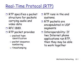
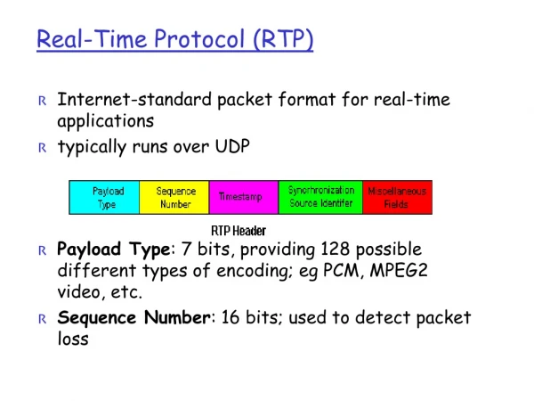
RTP specifies a packet structure for packets carrying audio and video data RFC 1889. RTP packet provides payload type identification packet sequence numbering timestamping. RTP runs in the end systems. RTP packets are encapsulated in UDP segments

Real-Time Protocol (RTP)
E N D
Presentation Transcript
RTP specifies a packet structure for packets carrying audio and video data RFC 1889. RTP packet provides payload type identification packet sequence numbering timestamping RTP runs in the end systems. RTP packets are encapsulated in UDP segments Interoperability: If two Internet phone applications run RTP, then they may be able to work together Real-Time Protocol (RTP) Multimedia Networking
RTP runs on top of UDP • RTP libraries provide a transport-layer interface • that extend UDP: • port numbers, IP addresses • payload type identification • packet sequence numbering • time-stamping Multimedia Networking
Consider sending 64 kbps PCM-encoded voice over RTP. Application collects the encoded data in chunks, e.g., every 20 msec = 160 bytes in a chunk. The audio chunk along with the RTP header form the RTP packet, which is encapsulated into a UDP segment. RTP header indicates type of audio encoding in each packet sender can change encoding during a conference. RTP header also contains sequence numbers and timestamps. RTP Example Multimedia Networking
RTP and QoS • RTP does not provide any mechanism to ensure timely delivery of data or provide other quality of service guarantees. • RTP encapsulation is only seen at the end systems: it is not seen by intermediate routers. • Routers providing best-effort service do not make any special effort to ensure that RTP packets arrive at the destination in a timely matter. Multimedia Networking
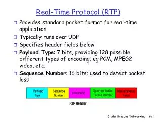
RTP Header • Payload Type (7 bits): Indicates type of encoding currently being used. If sender changes encoding in middle of conference, sender • informs the receiver through this payload type field. • Payload type 0: PCM mu-law, 64 kbps • Payload type 3, GSM, 13 kbps • Payload type 7, LPC, 2.4 kbps • Payload type 26, Motion JPEG • Payload type 31. H.261 • Payload type 33, MPEG2 video • Sequence Number (16 bits): Increments by one for each RTP packet • sent, and may be used to detect packet loss and to restore packet • sequence. Multimedia Networking
Timestamp field (32 bytes long). Reflects the sampling instant of the first byte in the RTP data packet. For audio, timestamp clock typically increments by one for each sampling period (for example, each 125 usecs for a 8 KHz sampling clock) if application generates chunks of 160 encoded samples, then timestamp increases by 160 for each RTP packet when source is active. Timestamp clock continues to increase at constant rate when source is inactive. SSRC field (32 bits long). Identifies the source of the RTP stream. Each stream in a RTP session should have a distinct SSRC. RTP Header (2) Multimedia Networking
RTSP/RTP Programming Assignment • Build a server that encapsulates stored video frames into RTP packets • grab video frame, add RTP headers, create UDP segments, send segments to UDP socket • include seq numbers and time stamps • client RTP provided for you • Also write the client side of RTSP • issue play and pause commands • server RTSP provided for you Multimedia Networking
Works in conjunction with RTP. Each participant in RTP session periodically transmits RTCP control packets to all other participants. Each RTCP packet contains sender and/or receiver reports report statistics useful to application Statistics include number of packets sent, number of packets lost, interarrival jitter, etc. Feedback can be used to control performance Sender may modify its transmissions based on feedback Real-Time Control Protocol (RTCP) Multimedia Networking
RTCP - Continued - For an RTP session there is typically a single multicast address; all RTP and RTCP packets belonging to the session use the multicast address. - RTP and RTCP packets are distinguished from each other through the use of distinct port numbers. - To limit traffic, each participant reduces his RTCP traffic as the number of conference participants increases. Multimedia Networking
Receiver report packets: fraction of packets lost, last sequence number, average interarrival jitter. Sender report packets: SSRC of the RTP stream, the current time, the number of packets sent, and the number of bytes sent. Source description packets: e-mail address of sender, sender's name, SSRC of associated RTP stream. Provide mapping between the SSRC and the user/host name. RTCP Packets Multimedia Networking
RTCP can synchronize different media streams within a RTP session. Consider videoconferencing app for which each sender generates one RTP stream for video and one for audio. Timestamps in RTP packets tied to the video and audio sampling clocks not tied to the wall-clock time Each RTCP sender-report packet contains (for the most recently generated packet in the associated RTP stream): timestamp of the RTP packet wall-clock time for when packet was created. Receivers can use this association to synchronize the playout of audio and video. Synchronization of Streams Multimedia Networking
RTCP attempts to limit its traffic to 5% of the session bandwidth. Example Suppose one sender, sending video at a rate of 2 Mbps. Then RTCP attempts to limit its traffic to 100 Kbps. RTCP gives 75% of this rate to the receivers; remaining 25% to the sender The 75 kbps is equally shared among receivers: With R receivers, each receiver gets to send RTCP traffic at 75/R kbps. Sender gets to send RTCP traffic at 25 kbps. Participant determines RTCP packet transmission period by calculating avg RTCP packet size (across the entire session) and dividing by allocated rate. RTCP Bandwidth Scaling Multimedia Networking
SIP • Session Initiation Protocol • Comes from IETF SIP long-term vision • All telephone calls and video conference calls take place over the Internet • People are identified by names or e-mail addresses, rather than by phone numbers. • You can reach the callee, no matter where the callee roams, no matter what IP device the callee is currently using. Multimedia Networking
Setting up a call Provides mechanisms for caller to let callee know she wants to establish a call Provides mechanisms so that caller and callee can agree on media type and encoding. Provides mechanisms to end call. Determine current IP address of callee. Maps mnemonic identifier to current IP address Call management Add new media streams during call Change encoding during call Invite others Transfer and hold calls SIP Services Multimedia Networking
Setting up a call to a known IP address • Alice’s SIP invite message indicates her port number & IP address. Indicates encoding that Alice prefers to receive (PCM ulaw) • Bob’s 200 OK message indicates his port number, IP address & preferred encoding (GSM) • SIP messages can be sent over TCP or UDP; here sent over RTP/UDP. • Default SIP port number is 5060. Multimedia Networking
Codec negotiation: Suppose Bob doesn’t have PCM ulaw encoder. Bob will instead reply with 606 Not Acceptable Reply and list encoders he can use. Alice can then send a new INVITE message, advertising an appropriate encoder. Rejecting the call Bob can reject with replies “busy,” “gone,” “payment required,” “forbidden”. Media can be sent over RTP or some other protocol. Setting up a call (more) Multimedia Networking
Example of SIP message • Here we don’t know • Bob’s IP address. • Intermediate SIPservers will be necessary. INVITE sip:bob@domain.com SIP/2.0 Via: SIP/2.0/UDP 167.180.112.24 From: sip:alice@hereway.com To: sip:bob@domain.com Call-ID: a2e3a@pigeon.hereway.com Content-Type: application/sdp Content-Length: 885 c=IN IP4 167.180.112.24 m=audio 38060 RTP/AVP 0 Notes: • HTTP message syntax • sdp = session description protocol • Call-ID is unique for every call. • Alice sends and receives SIP messages using the SIP default port number 506. • Alice specifies in Via:header that SIP client sends and receives SIP messages over UDP Multimedia Networking
Caller wants to call callee, but only has callee’s name or e-mail address. Need to get IP address of callee’s current host: user moves around DHCP protocol user has different IP devices (PC, PDA, car device) Result can be based on: time of day (work, home) caller (don’t want boss to call you at home) status of callee (calls sent to voicemail when callee is already talking to someone) Service provided by SIP servers: SIP registrar server SIP proxy server Name translation and user locataion Multimedia Networking
SIP Registrar • When Bob starts SIP client, client sends SIP REGISTER message to Bob’s registrar server (similar function needed by Instant Messaging) REGISTER sip:domain.com SIP/2.0 Via: SIP/2.0/UDP 193.64.210.89 From: sip:bob@domain.com To: sip:bob@domain.com Expires: 3600 Register Message: Multimedia Networking
SIP Proxy • Alice sends invite message to her proxy server • contains address sip:bob@domain.com • Proxy responsible for routing SIP messages to callee • possibly through multiple proxies. • Callee sends response back through the same set of proxies. • Proxy returns SIP response message to Alice • contains Bob’s IP address • Note: proxy is analogous to local DNS server Multimedia Networking
Example Caller jim@umass.edu with places a call to keith@upenn.edu (1) Jim sends INVITEmessage to umass SIPproxy. (2) Proxy forwardsrequest to upenn registrar server. (3) upenn server returnsredirect response,indicating that it should try keith@eurecom.fr (4) umass proxy sends INVITE to eurecom registrar. (5) eurecom registrar forwards INVITE to 197.87.54.21, which is running keith’s SIP client. (6-8) SIP response sent back (9) media sent directly between clients. Note: also a SIP ack message, which is not shown. Multimedia Networking
H.323 is another signaling protocol for real-time, interactive H.323 is a complete, vertically integrated suite of protocols for multimedia conferencing: signaling, registration, admission control, transport and codecs. SIP is a single component. Works with RTP, but does not mandate it. Can be combined with other protocols and services. H.323 comes from the ITU (telephony). SIP comes from IETF: Borrows much of its concepts from HTTP. SIP has a Web flavor, whereas H.323 has a telephony flavor. SIP uses the KISS principle: Keep it simple stupid. Comparison with H.323 Multimedia Networking


![[Lab] Real-Time Transport Protocol (RTP)](https://cdn5.slideserve.com/9443037/lab-real-time-transport-protocol-rtp-dt.jpg)