Reducing ATE Test Time with Asynchronous Clocking in Advanced CMOS VLSI Technologies
This paper presents a novel methodology for reducing Automated Test Equipment (ATE) test time by dynamically varying the test clock rate according to per-cycle energy dissipation. We demonstrate how this innovative approach, employing asynchronous clock testing, can effectively minimize test time while maintaining power constraints in low-power CMOS VLSI applications. By analyzing synchronous and asynchronous testing techniques for various scan tests, we establish the potential for significant time savings when implementing our proposed method at Auburn University.

Reducing ATE Test Time with Asynchronous Clocking in Advanced CMOS VLSI Technologies
E N D
Presentation Transcript
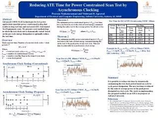
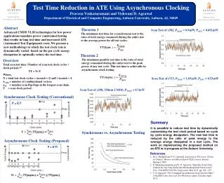
Test Time Reduction in ATE Using Asynchronous Clocking • Praveen Venkataramani and Vishwani D. Agrawal • Department of Electrical and Computer Engineering, Auburn University, Auburn, AL 36849 Abstract Advanced CMOS VLSI technologies for low power applications mandate power constrained testing that results in long test time and increased ATE (Automated Test Equipment) costs. We present a new methodology in which the test clock rate is dynamically varied based on the per cycle energy dissipation to optimally reduce the test time. Theorem 1 The minimum test time for a synchronous test is the ratio of total energy consumed during the entire test to the average power for all test cycles. Scan Test of s382, PMAX = 0.9mW, PAVG= 0.692mW Theorem 2 The minimum possible test time is the ratio of total energy consumed during the entire test to the peak power of any test cycle. This test time is achievable by asynchronous clock testing: Overview Total scan test time (Number of scan test clock cycles × clock period):[1] TT = N×T Where, N = total test clock cycles = (ncomb + 2) nsff + ncomb + 4 ncomb= number of combinational vectors nsff= number scan flip-flops in the longest scan chain T = scan clock period Scan Test of s713, PMAX = 1.03mW, PAVG = 0.53mW Scan Test of s298, 350nm CMOS, PMAX= 0.7mW Synchronous Clock Testing (Conventional) P = E/T Summary It is possible to reduce test time by dynamically customizing the test clock period based on cycle by cycle energy dissipation. The new test time is reduced by the ratio of peak energy to the average energy dissipated in a test cycle. The work on implementing the proposed method on an ATE is in progress at the Auburn University. , TT(sync.) = Synchronous vs. Asynchronous Testing Asynchronous Clock Testing (Proposed) P = E/Ti References M. L. Bushnell and V. D. Agrawal, Essentials of Electronic Testing for Digital, Memory and Mixed-Signal VLSI Circuits. Boston: Springer, 2000. P. Shanmugasundaram and V. D. Agrawal, “Dynamic Scan Clock Control for Test Time Reduction Maintaining Peak Power Limit,” Proc. 29th IEEE VLSI Test Symposium, May 2011, pp. 248 –253. V. D. Agrawal, “Pre-Computed Asynchronous Scan (Invited Talk),” 13th IEEE Latin American Test Workshop, Quito, Ecuador, April 2012. , TT(async.) = ≤ TT(sync.)