PANTHR Hybrid Rocket
PANTHR Hybrid Rocket. Final Design Review December 6 th 2006. PANTHR Team Members. Glen Guzik Niroshen Divitotawela Michael Harris Bruce Helming David Moschetti Danielle Pepe Jacob Teufert. Current Division of Labor.

PANTHR Hybrid Rocket
E N D
Presentation Transcript
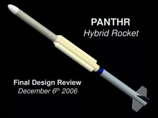
PANTHRHybrid Rocket Final Design ReviewDecember 6th 2006
PANTHR Team Members Glen Guzik Niroshen Divitotawela Michael Harris Bruce Helming David Moschetti Danielle Pepe Jacob Teufert
Current Division of Labor • Hybrid Motor Design- Niroshen Divitotawela- Michael Harris- Jacob Teufert • Aerodynamics and Flight Stability- Bruce Helming- Danielle Pepe • Payload and Recovery- Glen Guzik- Bruce Helming - Danielle Pepe - Michael Harris • Structural Analysis- David Moschetti - Niroshen Divitotawela • Safety and Logistics-David Moschetti-Glen Guzik
Primary Project Objectives • Build hybrid rocket motor - paraffin fuel (CnHm; n~25, m~50) - nitrous oxide oxidizer (N2O) • Conduct static test fire • Complete fabrication of rocket • Launch rocket to an altitude of ~12,000 ft. • Collect various in-flight data- acceleration curve- flight trajectory- altitude at apogee- onboard flight video
The Paraffin Advantage Advantages of Paraffin • High Regression Rate • Practical Single-Port Design • High Energy Density (~same as kerosene) • Inexpensive • Non-toxic Advantages of Nitrous Oxide • Available • Inexpensive • Self-Pressurizing
MOTOR EXPLODED VIEW OXIDIZER TANK ABLATIVE LINER INJECTOR FUEL GRAIN NOZZLE COMBUSTION CHAMBER
Oxidizer Fill and Ignition System • Fill internal oxidizer tank via external, commercial nitrous-oxide tank. • Light solid propellant ignition charge via electric match.
Trajectory Analysis • 1 Degree of Freedom • Explicit First-Order Finite Difference Method • Thrust and Mass=f(t) • Drag=f(v) • Density=f(h)
Regression Rate • Use regression rate formula for hybrids • a = .155, n=.5 [1] • Regression Rate = 1.98 mm/s [1] AA283 Aircraft and Rocket Propulsion – Hybrid Rockets. Stanford University Department of Aeronautics and Astronautics. 2004
Combustion Chamber Dimensioning From Trajectory Analysis: • Average Mass Flow: 0.375 kg/s • Burn Time: 4 s From Literature Review: • Regression rate as f(dm/dt) • Oxidizer/Fuel Ratio Results: • Grain Thickness (d=rtb) • Grain Length
Combustion Chamber Dimensions • Grain Length: 4.2” • Grain Thickness: 0.68” • Chamber Wall Thickness: 1/8” • Ablative Liner Thickness: 1/8” 3.0” Combustion Chamber Ablative Liner Fuel Grain 4.2” 1.14”
Combustion Chamber Thermodynamic Properties From Analysis • Adiabatic Flame Temperature: 3800K From Literature Review • Paraffin Flame Temperature: 1700K For Design • Average Value: 2750K
Nozzle Design • Method • Decided to expand the flow to sea-level pressure. • Use of isentropic relations • Find the Area Ratio • From trajectory computation make use of estimate of mass flow rate.
Specifications • Conical Nozzle • Ae/A* = 3.64 • Divergence Angle of 8o • Length 3.87” • Weight 1.13 lbs.
Trade Study • Several Alloys were compared in the decision process for the material of the tubing needed for the tank. • Al 6061-T6 was observed to be the best metal to use considering cost and strength. Ratings were acquired by the Hadco Aluminum website.
Structural Analysis • Most severely stressed components are the Combustion Chamber and Oxidizer Tank • Wall Thickness was calculated using hoop stress equation With F.S. of 2:
Max hoop stress (ANSYS) = 9640 psi • Max hoop stress (Theory) = 10000 psi
Structural Analysis • We are using 8 bolts the attach each bulkhead • Each bolt is made of 1022 Carbon Steel • The Allowable Shear for each bolt is 29,000 psi Total Force acting on Bulkheads: Shear on each Bolt:
Structural Analysis Bearing Stress Yield: • The Bearing Stress was calculated for the aluminum tube using the force of the load distributed to each bolt • With that the calculation divides the load by the thickness of the wall, diameter of each hole, and the number of bolts • The allowable was found to be 1.5 times the allowable Tensile strength Total Bearing Stress:
Payload Data Collection • Acceleration versus time in 3 dimensions • Pressure versus time • Flight video at 30 FPS 352 x 240
Payload Drop Test • Launch zone, “The Grid” • Impact velocity of up to 25 ft/s • Equivalent to a drop from 10 ft • Survive landing on: trees, rocks, grass, and asphalt
Stability • Maintain the Static Margin • Options: - Under-damped - Neutral - Over-damped • Current Configuration: - over-damped http://www.rockets4schools.org/education/Rocket_Stability.pdf
Stability • Subsonic flight allows use of Barrowman Method • Xcp (Tail reference) = 14.45 inch • Xcg (Tail reference) varies between 34.26 – 38.25 inches
Fin Design • 3 different fin designs based on initial rocket plans • Flutter conditions accounted for • Wind tunnel testing was performed
Fin Specifications • Dimensions based on flutter analysis, testing, and stability calculations: • Cr = 6” • Ct = 2.5” • S = 4” • t = 0.167” Ct S Cr
Types of Nose Cones 1) Elliptical 2) Conical • They both have low drag characteristics in low-transonic Mach regions. • Elliptical Shape • Total Drag From Experiment = 0.029 • Small Length and Weight decrease Static Margin • Conical Shape • Total Drag From Experiment =0.041 • Length and Weight increase Static Margin Final Choice: Elliptical http://myweb.cableone.net/cjcrowell/NCEQN2.DOC
Recovery Nosecone • Barometric Altimeter • Drogue Chute – Deploys at apogee • Main Chute – Deploys when altimeter detects specified altitude (~1500ft) Drogue Parachute Main Parachute Cut Away View
Spring Semester 2007 Milestones • February 12th: Complete Motor Construction • February 18th: Static Test Fire • February 26th: Complete Payload Construction • March 13th: Payload Drop Test • March 22nd: Rocket Fabrication Finalized • Launch 2nd Week of April
Safety Plan Main Risks • High Pressure Systems • Chemicals/Flammables • Test Fire and Launch Procedures • Construction Mitigation Plan • Currently working with the University Safety Office on developing procedures for handling, construction, and launch of the rocket.