Download
1 / 15
150 likes | 272 Vues
This document presents a comprehensive root cause analysis (RCA) of the static line failure incident that occurred on December 1, 2002, at the Palisades Nuclear Plant. The analysis identifies mechanical wear and inadequate preventive maintenance over 30 years as the primary causes of the failure, leading to a loss of load and subsequent reactor trip. Detailed evaluations of previous similar events, safety significance, and corrective actions are discussed. The findings underscore the need for improved maintenance practices to prevent future incidents of this nature.

E N D
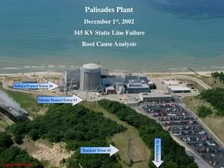
PalisadesPlant December 1st, 2002 345 KV Static Line Failure Root Cause Analysis Tubular Framed Tower #4 Tubular Framed Tower #3 Standard Tower #2 To Switchyard August 2002 Photo
Palisades Nuclear Plant Root Cause Evaluation RCE for CAP032289 “Automatic Reactor Trip and AFAS Actuation.” Prepared by: JRTilton / DLAndersen Date: 12/11/02@1400hrs DRAFTin.ppt@K:/SysEng/RootCause. Approved by: DDCrabtree Date: 2
Table of Contents • Executive Summary 4 • Introduction and Methodology 7 • Evaluation Results 7 • Root Cause Statements 10 • Previous Similar Events/Recurring Events 10 • Safety Significance, Extent of Condition and Generic Implications 11 • Corrective Actions 13 VIII. Attachments 15 3
I.Executive Summary At 2154 Sunday evening, December 1, 2002, the plant tripped from 100% power on “Loss of Load”. Inadequate preventive maintenance over a 30 year service life resulted in failure of the static line hanger “dog bone” at its connection to Tower #2. Failed Static Wire Swivel Worn Through Dog-Bone Wire Shoe Static Wire Step 1 Tower #3 Tower #2 R- Bus Tower #1 Xfmr Tower #4 Switchyard Dunes Protected Area Tower #2 Failed Dog-Bone Only the ‘X’ Phase 345KV & 1 Static Line Shown for drawing simplicity 345 KV Line shown in Red Static line shown in Blue 4
Step 2 Tower #3 Tower #2 R- Bus Tower #1 Tower #4 Switchyard Dunes Protected Area The release of the static line from Tower #2 created an additional mechanical load / weight between Towers # 1 and #3 causing a similar failure of the “dog bone” and the pin/shoe connection on Tower #1. The sagging static line contacted the “X” phase conductor of the 345KV transmission line east of Tower #3. From Tower #2 Failed Shoe Tower #1 Failed Dog-Bones Towers 1 & 2 From Tower #1 Step 2 5
Step 3 Step 3 Step 3 Tower #2 Tower #3 R-Bus Tower #1 Tower #4 Switchyard Dunes Protected Area The 345KV energy now traveling through the static line caused a section of the static line to vaporize back toward Tower #3. At 2154:19 loss of load (345KV to ground) tripped the main generator and initiated a fast transfer of Buses 1A, 1B, 1G and 1F to startup power. The now severed static line fell further and contacted the switchyard "R" bus. At 2154:21 R-Bus tripped on a fault to ground further resulting in loss of the A, B, F, and G, 4160VAC busses. This caused the loss of all primary coolant pumps. Plant equipment responded well to the initial trip. The plant went to natural circulation mode of operation and was maintained at or near normal operating pressure (about 2060psia) and operating temperature (about 535 degrees F). No indications of terrorist activity, vandalism or sabotage were found during investigations following the incident. All evidence gathered is consistent with a mechanical wear failure mechanism. Severed ends of static line Static line on R-Bus Static line R-Bus R-Bus End from Tower #3 End found on ground 6
Fresh Markings Show Release Point Old Rusted Wear PROBLEM STATEMENT: The north static wire fell contacting the main transmission line on its route from the plant to the switchyard and the R-Bus resulting in a Loss of Load trip of the main generator and a loss of the R-Bus. Determine the root cause(s) and the sequence of events. II. Introduction and Methodology The evaluation included an inspection of the failed components, a historical review looking at original design, preventive maintenance activities, previous condition reports, and work orders for items involving the transmission line between the Plant and the Switchyard. Engineering, Operations, Security and Maintenance personnel were interviewed. Events Log Recorder, Sequence of Events Log, System Protection Events records and the Post Trip Report were reviewed to develop a sequence of pertinent activities and events. The accumulated information was analyzed and assembled into a failure scenario to identify the failure mechanism and root cause(s). • Evaluation Results Visual inspection of the failed static line connection hardware from the Tower #2’s north arm found a ductile failure of the “dog bone” upper eye where it connected to the “U” - bolt on the tower arm. The dark oxidized surface of the wider groove indicates this wear has been occurring over a long period of time. The bright fracture surfaces at the ends of the drawn material indicate the failure as a recent event. There is no indication of arcing on the dog-bone swivel, which supports the premise that the static line contacted the 345KV line after the dog-bone separated from the tower. 7
Failed Static Wire Dog-Bone Ends Worn and Failed Dog-Bone From Tower #2 Worn and Failed Dog-Bone From Tower #1 Excessively Worn Shoe Broke at Pin Hole Fresh Break Tower #1 Shoe Visual inspection of the failed static line connection hardware from Tower #1 found a similar ductile failure of the “dog bone” upper eye and an additional failure of the pin/shoe connector. The dark oxidized surface of the wider groove of the “dog bone” upper eye indicates this wear has also been occurring over a long period of time. The bright fracture surfaces at the ends of the drawn material indicate this also as a recent failure. The additional break of the shoe connector at Tower #1 indicated that this connection was subjected to more force, since there were two failures associated with it. The connector failed in two locations due to the abrupt increase in load caused by the static line falling from Tower #2. Also, the dog-bone from Tower #1 has less wear than the dog-bone from Tower #2, further supporting the premise that Tower #2 connection failed first. 8
End left attached to Tower #3 End on the ground The static line was found severed between Tower #2 and Tower #3. Both ends of the severed portion of the static line indicate the cable was cut by a heat source. The melted / welded end of the static line stub hanging from Tower #3 indicates intense heat had been applied. When the static line contacted the X- phase conductor of the 345KV transmission line, it is believed a section of the static line vaporized causing the witnessed high intensity flash and the melting of the remaining ends of the line. System Protection Events records showed at 2154:19:331, the 345KV line tripped due to a single line-to-ground fault on the X- Phase. Visual inspection of the 345KV transmission line conductors found a 50 – 60 foot section splattered with a silver colored material (similar to flicking a paint brush at them) that would be consistent with a line vaporization event. Failed Static Wire After the static line severed, it fell onto the R-Bus. System Protection Events records showed at 2154:21:563, the Palisades R-Bus tripped due to a single line-to-ground fault on the X- Phase. Plant equipment responded well to the trip. The plant went to natural circulation mode of operation and was maintained at or near normal operating pressure (about 2060psia) and operating temperature (about 535 degrees F). No indications of terrorist activity, vandalism or sabotage were found during investigations following the incident. All evidence gathered is consistent with a failure mechanism of mechanical wear over many years. 9
IV. Root Cause Statements Less than adequate rigor by Palisades to identify all equipment requiring inspections and inspection intervals, led to inadequate preventive maintenance to the transmission towers and associated equipment, located between the Palisades Turbine Building and the switchyard. Failure Scenario: Inadequate preventive maintenance over a 30 year service life allowed mechanical wear of the “dog bone” to the point of ductile failure at Tower #2. The additional mechanical load / force of the falling line between Towers # 1 and #3 caused a similar failure of the “dog bone” and the pin/shoe connection on Tower #1. The sagging static line contacted the “X” phase conductor of the 345KV transmission line east of Tower #3. The 345KV energy now traveling through the static line caused a section of the static line to vaporize back toward Tower #3. At 2154:19 Loss of load (345KV to ground) tripped the main generator. The now severed static line continued to fall and contacted the switchyard "R" bus. At 2154:21 R-Bus tripped on a fault to ground further resulting in loss of the A, B, F, and G, 4160VAC busses. This caused the loss of all primary coolant pumps. The plant went to natural circulation mode of operation and was maintained at or near normal operating pressure (about 2060psia) and operating temperature (about 535 degrees F). V. Previous Similar Events/Recurring Events At Palisades, no records or recollection of similar initiating events (transmission line failures) were found. However, E-PAL-87-33 (LER 87-0224), “Loss of Offsite Power due to fault on the S/U Xfmr 1-2” and CAP030535 (CPAL0202236), “Loss of ‘R’ bus due to Y-phase fault“ were similar to this event by their loss of R-Bus. Although they have different failure modes, the lightening arrestor failure was also attributed to inadequate preventive maintenance and this generic issue will be addressed by the corrective action to reassess SOER 99-1, Recommendation 3. Ludington Pumped Storage Plant had a similar “near miss” incident on October 14, 1995 where a static line “dog bone” failed and the static line fell. The static line fell onto an arm of the tower that prevented it from contacting a conductor and creating an equipment trip incident. No incident report was distributed and Palisades’ personnel were not aware of it until after this current failure. A copy of the Operating Experience Report will be provided the Palisades Asset Manager for distribution within their system. 10
SOER 99-1, Recommendation #3 focused on the switchyard components and did cite preventive maintenance inspections of the transmission lines between the plant and the switchyard where this failure occurred. PPAC MSE006, PM-345KV Towers and Transformers performs an annual visual inspection of the lines between the plant and the switchyard with field glasses. However the PPAC does not address / include steps to inspect the various line hangers and associated equipment. Further, the mechanical wear that precipitated this event would be difficult, if not impossible, to discern from the ground level with field glasses. INPO web site search for “static line” yielded 3 of 33 hits involving static lines falling. • A 1988 incident at Byron was caused by an electrical insulator mechanical failure due to severe direct lightning damage. • A 1989 incident at River Bend was caused by a static line failure due to a deficient pole ground connection to the static line. • A 1994 incident at River Bend was caused by failure of a grounding attachment that resulted in strand breakage over time. Corrective actions in these incidents involved repairs to the failed static lines and connections similar to those in this report. VI. Safety Significance, Maintenance Rule Implications, Extent of Condition and Generic Implications Safety Significance In the transmission and distribution routine, failure of a static line causing a fault to ground on transmission conductors is an uncommon (rare) occurrence. System protection devices are highly effective at protecting major equipment from damage and provide flexibility in rerouting of power keeping service interruptions short. The cost benefits of an extensive and intensive preventive maintenance program are not obvious for miles of transmission lines. However, at a nuclear plant, such failures present significant challenges to the operating staff. Outgoing Operating Experience item will identify this for the nuclear industry. Probabilistic Safety Assessment of this event (loss of “R” bus and loss of all primary coolant pumps) has been determined a non-significant safety impact at Palisades. (Reference TM-2002-022) No indications of terrorist activity, vandalism or sabotage were found during investigations following the incident. 11
Maintenance Rule Implications This event should be considered a Maintenance Rule Functional Failure (MRFF) of Switchyard Function #2, "Provide 345kV connection between the switchyard and the high side of the plant transformers," because the function of the 345KV connection was lost during this event. This Functional Failure is considered a Maintenance Preventable Functional Failure (MPFF) because it should have been prevented by the performance of appropriate maintenance actions on the static line. Extent of Condition DBD - 6.02, section 3.2.5 describes Lightning Protection as, “two overhead grounded shield lines for lightning protection.” The remaining static line was inspected and worn parts were replaced to prevent a similar event from this line. Also, the connections and conductors of the 345 KV lines were inspected with no anomalies identified requiring maintenance repair activities. Temporary Modification TM-2002-022 was developed to justify running with a single static line until the 2003 refueling outage. Oil samples from the main transformer EX-10 were analyzed and found satisfactory. 12/02/02 @ 1439 A CMS System Protection e-mail to Palisades Systems Engineering stated, “A review of System Protection’s short circuit program indicates that the 345kV circuit that connects the plant to the switchyard has minimal impedance compared to the main step-up transformer, therefore was not included in the short circuit model. Therefore, elimination of one of the two static wires between the plant and the switchyard has no effect on the short circuit results used in the calculations to set the associated protective devices. As a result, its absence does not affect any of the protective devices in the plant or switchyard. From a protective relaying perspective the main purpose of the static wire is to provide a lightning deterrent for the transmission line. Temporary removal of the second static wire may increase the potential for lightning strikes on this line segment. Although, the increased exposure during this time of the year should be minimal.” 12/02/02 @ 1543 A CMS Transmission & Distribution e-mail to Palisades Systems Engineering stated, “…. We concur that the 345KV transmission line can be safely re-energized and operated for several months with the broken static wire temporarily removed and out-of-service. It should be re-installed at the next opportunity, hopefully before the next summer’s lightning season…. All of these electric grounding requirements are adequately met by the remaining shield wire on the 345KV transmission line, the earth grounding at each tower base, and the 2-500 MCM CU underground ground cables installed between the switchyard and the plant when the 345KV safeguard transformer was installed about 1990….” System Protection’s preliminary protective relaying report said, “All the switchyard relaying appears to have worked as designed….” arrived 12/3/02. 12
Generic Implications Preventive Maintenance activities on all high voltage equipment that Palisades is responsible for are covered in the corrective actions in this report. Corrective Actions Completed Remedial Corrective Actions: The remaining static line was inspected and worn parts were replaced to prevent a similar event from this line. Also, the connections and conductors of the 345 KV lines were inspected with no anomalies identified requiring maintenance repair activities. Oil samples from the main transformer EX-10 were analyzed and found satisfactory. Startup MRB was held 12/03/02 @ 1600 to review and accept the preliminary investigation results and approve a restart plan. Startup PRC was held 12/04/02 @ 0800 to review and accept the root cause results and approve a restart. TM-2002-22, “To accept the section of 345KV transmission line (north line, running between the Main Power Transformer and the Switchyard) without the static wire on top of it. The Static wire is to be installed during 2003 Refout, per its original design under the direction of personnel from the region. This TM will document the completion of its installation.” RJC, December 3, 2002. Remedial Corrective Actions: Coordinate with Transmission & Distribution Department personnel to replace the north static line section removed per TM-2002-22. MJCapaccio for 03Refout. Corrective Actions To Prevent Recurrence: Re-evaluate Palisades’ response to SOER 99-1, “Loss of Grid”, Recommendation #3. (Includes obtaining Regional Transmission & Distribution recommendations and incorporating their input into Plant inspections of transmission and static lines from the switchyard to the plant). EHKoepke 13
Other corrective actions: Request Regional Transmission & Distribution inspect transmission and static lines from the switchyard front bus out to the first transmission tower. DDCrabtree Request Regional Transmission & Distribution inspect transmission and static lines from the switchyard out beyond the first transmission tower. GCPackard Perform an effectiveness review of RCE000311corrective actions by reviewing inspections performed and available industry experience for an indications of potential hardware failures resulting in “Loss of Grid” not covered at Palisades. CAP 032327 was initiated December 3, 2002 to ensure that a post trip critique is conducted to capture any human performance issues or lessons learned from this event. No Operations Human Performance issues immediately apparent from the Post Event Report following the December 1, 2002 trip. Items to consider in the evaluation include the following: Control room manning requirements, since only one NCO was in the CR at the time of the trip, as is allowed by procedures. Any training successes and/or needs based on operator comments on the use of GCL 10.2 and on the use of auxiliary spray with a spray valve stuck open. DJVandewalle by January 3, 2003. CA017677 was initiated on December 4, 2002 to submit preliminary Operating Experience to INPO and initiate an action to provide follow up data to INPO when available. LLLewis by January 23, 2003. 14
VII. Attachments Personnel Assisting or Interviewed Palisades Security Consultant Wackenhut Security Operations Coordinator Wackenhut Security Officers Design Engineering Condition Review Team Leader Operations Condition Review Team Leader Operations Procedures Writer Maintenance Support Supervisor Programs & Analysis Engineering Supervisor Programs & Analysis Engineering Technical Lead System Protection Engineers Electric System Design Engineer Electric System Operations Supervisor Electric Network Services, Lines Construction Lead Ludington Pumped Storage Plant, Engineer Documents Reviewed SOER 99-1, “Loss of Grid” DBD - 6.02, “345KV Switchyard” System Protection: Trip Analysis Report, 2002-127. Laboratory Services: Transformer Oil Test Report, 12/2/2002. Post Event Review Report 12/02/02 @ 1439, System Protection e-mail to Palisades Systems Engineering 12/02/02 @ 1543, Electric System Design e-mail to Palisades Systems Engineering 15