Crack Mitigation
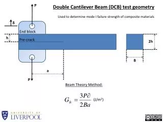
Crack Mitigation. Principle Techniques for Crack Mitigation Planning the layout of restraining members Structural separations Closure strips, joints and favorable pour sequencing Released Connections Addition/improved layout of rebar. Shear Wall. COLUMN. WALL.

Crack Mitigation
E N D
Presentation Transcript
Crack Mitigation • Principle Techniques for Crack Mitigation • Planning the layout of restraining members • Structural separations • Closure strips, joints and favorable pour sequencing • Released Connections • Addition/improved layout of rebar
Shear Wall COLUMN WALL (a) FAVORABLE ARRANGEMENT OF RESTRAINING WALLS (b) UNFAVORABLE ARRANGEMENT OF RESTRAINING WALLS SHEAR WALL ARRANGEMENT AND CRACK FORMATION
Crack Mitigation • Principal Functions of Post-Tensioning • Provide uplift • Contribute to the ultimate strength of the section • Provide precompression
Crack Mitigation • Major Functions of Precompression • Mitigate Cracking • Reduce Deflections • Impart Two-Way Action • Improve Punching Shear Performance
Crack Mitigation • Precompression is partially or totally lost at location of cracks • Ultimate strength of a section is not a function of precompression
Shrinkage/Creep/ Cracks • Summary of Observations • Cracks do not impair strength of slab • Cracks do not commonly lead to excessive deflections • Cracks increase exposure to Corrosion
Recommendations MOST CRACKS ARE NOT STRUCTURALLY SIGNIFICANT SEAL OFF CRACKS OF EXCESSIVE WIDTH (GREATER THAN .01 INCH) PARTICULARLY WHERE DURABILITY AND CORROSION ARE IMPORTANT CONSIDERATIONS (EXPOSED STRUCTURE)
Repair Cracks • Purpose of Repair • Mostly to cut off exposure of reinforcement and tendons to moisture and weather • Rarely to restore integrity to structure • Occasionally for aesthetic reasons
Repair Cracks • Which Cracks to Repair? • Cracks which are determined to be structurally significant • Cracks which are wider than 0.01 inch • All cracks if slab is subjected to highly aggressive environment
Repair Cracks • When to Repair • Repair shrinkage/creep cracks two years after construction if corrosion considerations allow
Repair Cracks • How to Repair • If crack is dormant – inject low epoxy resin under pressure • If crack is working – rout a groove along cracks and fill with flexible sealant to withstand movement
Conclusions and Recommendations • General Conclusions • The most common impairment of shortening cracks is exposure of rebar and tendons to corrosive elements • For slabs with significant support restraints, such as perimeter walls, it is often times necessary to conduct a one time maintenance routine to repair shortening cracks
Conclusions and Recommendations • Crack Formation Can Be Controlled and Significantly Reduced • Planning and layout of constraint • Structural separations • Closure strips, joints and pour sequencing • Released connections • Addition/improved layout of rebar • Addition/improved layout of tendons
Conclusions and Recommendations • Recommendations • For slabs supported on regular sized columns: • If slab is regular and small (1500 sq.ft. or less) design slab to withstand forces generated by shortening • For slabs with substantial restraints, • Implement crack mitigation measures • Implement a one time maintenance procedure
Conclusions and Recommendations • Add notes on structural drawing indicating that: • Shortening cracks are likely to occur • Shortening cracks do not normally impair structural integrity of the slab • Slab should have a one time crack maintenance operation
Conclusions and Recommendations • Maintenance Program • Inspect and evaluate slabs and supporting structures two years after construction • Determine cracks to be repaired • Repair cracks
Conclusions and Recommendations • Describe the crack maintenance scheme on the structural drawings • Estimate the total length of anticipated cracks requiring repair (such as 0.009 ft. per sq. ft. of slab for subterranean slabs) • Specify who should allow funds to be dispersed for the maintenance program • Estimate funds to allocate for maintenance program (such as $8.00 per ft. of crack, or 70 per sq. ft. of slab)
Conclusions and Recommendations • Remarks on water and moisture penetration through slabs and supporting element
WJ WJ WJ WALL CLOSURE STRIP WJ WJ WJ (a) PLAN SHOWING WALL JOINTS(WJ) AND CLOSURE STRIP ABOVE PERMANENT RELEASE FULL TIE WALL CLOSURE 110 ft. SLAB STRIP NO TIE 230 ft. (b) PLAN SHOWING ARRANGEMENT OF DIFFERENT WALL/SLAB CONNECTIONS
PT SLAB SLIP JOINT WALL JOINT WALL FOOTING ELEVATION OF CORNER WALL SHOWING WALL JOINT
SHEAR WALLS 230 ft. 230 ft. (a) PLAN OF SLAB WITH FOUR CORNER SHEAR WALLS
CLOSURE CLOSURE STRIP STRIPS (b) ALTERNATIVE PLANS FOR PLACEMENT OF CLOSURE STRIPS
Conclusions and Recommendations • Remarks on release joints • Implementation of releases in slabs improves the serviceability at the cost of reducing the strength reserve against failure under catastrophic loadings.
Principal Techniques for Crack Mitigation • Planning the layout of restraining members • Structural separations • Closure strips, joints and favorable pour sequencing • Released Connections • Addition/improved layout of rebar • Addition/improved layout of tendons
Shear Walls SLAB 9'-0" WALL SHRINKAGE/ CREEP REBAR CRACK MITIGATING REBAR NEXT TO SHEAR WALLS
Shear Walls REBAR WALL (a) INTERIOR SHEAR WALL REBAR (b) EXTERIOR SHEAR WALL CRACK MITIGATING REBAR NEXT TO SHEAR WALLS
Slab Corners REBAR WALL SLAB REINFORCEMENT AT SLAB CORNERS
PRINCIPAL TECHNIQUES FOR CRACK MITIGATION • PLANNING THE LAYOUT OF RESTRAINING MEMBERS • 2. STRUCTURAL SEPERATIONS • 3. CLOSURE STRIPS, JOINTS AND FAVORABLE POUR SEQUENCING • 4. RELEASED CONNECTIONS • 5. ADDITION/IMPROVED LAYOUT OF REBARS • 6. ADDITION/IMPROVED LAYOUT OF TENDONS
64' 64' 64' COLUMN SLAB TENDONS SHEAR WALLS TENDON ARRANGEMENT TO COMPENSATE FOR RESTRAINING EFFECTS OF TRANSVERSE WALLS
WALL COLUMN SLAB TENDONS TENDON ARRANGEMENT FOR MITIGATING CRACKS IN CENTRAL SPANS
SLAB TENDON TENDON CRACK INHIBITING LAYOUT CRACK PROMOTING LAYOUT ARRANGEMENT OF TENDONS AT OPENING
INCOMPLETE OR POOR IMPLEMENTATION OF CRACK MITIGATION MEASURES MAY LEAD TO UNSUCCESSFUL RESULTS.
COMMON SHORTCOMINGS IN IMPLEMENTATION OF CRACK MITIGATION MEASURES
RESISTANCE SLIP JOINT DUE TO KEY SLAB MOVEMENT SLAB/BEAM GAP CONCRETE MASONRY UNIT CRACK PROVIDE COMPRESSIBLE RECOMMENDED MATERIAL CRACK FORMATION AT SLIP JOINT WHERE BEAM STEM KEYS INTO WALL
DIRECTION OF SLAB MOVEMENT END OF WALL SLAB SLIP JOINT WALL FOOTING CRACKS CRACKS AT END OF SLIP JOINTS
BEAM MOVEMENT REBAR BEAM CRACKS SLIP JOINT COLUMN WALL NO GAP INCORRECT IMPLEMENTATION OF SLIP JOINT
WIRE WRAPPING SLAB COMPRESSIBLE SLAB REINFORCEMENT MATERIAL SLIP JOINT DOWEL WALL (a) ELEVATION - SLAB REINFORCEMENT AT LEFT IS WRONGLY TIED TO RELEASE DOWEL COMPRESSIBLE MATERIAL WALL RELEASE CORRUGATED TUBE WALL DOWEL (b) BLOCKOUT TUBING PLACED WRONGLY OFF-CENTER INCORRECT EXECUTION OF SLAB/WALL RELEASE BLOCKOUTS
SLIP PAD SLAB WALL PENETRATES INTO SLAB CONCRETE MASONRY UNIT WALL INCORRECT IMPLEMENTATION OF SLIP JOINT IN LOAD BEARING WALL
EXAMPLES OF SUCCESSFUL IMPLEMENTATION OF CRACK MITIGATION MEASURES
CRACK TYPES AND CAUSES • CRACK MITIGATION • STRUCTURAL EVALUATION • OF CRACKS • 4. REPAIR CRACKS • 5. CONCLUSIONS AND • RECOMMENDATIONS
EVALUATE SLAB PERFORMANCE DUE TO CRACKS • SERVICEABILITY • DEFLECTION PROTECTION AGAINST CORROSION FREEZE-THAW DAMAGE • STRENGTH • FACTOR OF SAFETY AGAINST FAILURE
REVIEW THE ROLE OF POST-TENSIONING IN SLAB PERFORMANCE WITH THE OBJECTIVE TO DETERMINE WHICH CONTRIBUTION OF THE POST-TENSIONING ARE IMPAIRED DUE TO SLAB CRACKS
CONTRIBUTIONS OF POST-TENSIONING • PROVIDE UPLIFT • 2. CONTRIBUTE TO THE ULTIMATE STRENGTH OF THE SECTION • 3. PROVIDE PRECOMPRESSION
CONTRIBUTIONS OF POST-TENSIONING • PROVIDE UPLIFT • CONTRIBUTE TO THE ULTIMATE STRENGTH OF THE SECTION • PROVIDE PRECOMPRESSION
UPLIFT IS A FUNCTION OF 1. FORCE IN THE TENDON 2. PROFILE OF THE TENDON CRACKS IN THE SLAB NIETHER AFFECT THE TENDON FORCE NOR ITS PROFILE. HENCE THE UPLIFT IS NOT IMPAIRED.