KOTO CDT Module Status Report
100 likes | 124 Vues
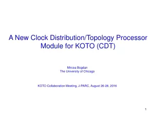
KOTO CDT Module Status Report. Mircea Bogdan The University of Chicago 10/13/2016. New CDT - Block Diagram – 8/27/2016. Minor changes to the Old MT Board: Same FPGA Same TLK chips The Changes are: 4 TLK Chips 16 x RJ45 to ADCs 2 x RJ45 to Master Clock Jitter Cleaner.

KOTO CDT Module Status Report
E N D
Presentation Transcript
KOTO CDT Module Status Report Mircea Bogdan The University of Chicago 10/13/2016
New CDT - Block Diagram – 8/27/2016 • Minor changes to the Old MT Board: • Same FPGA • Same TLK chips • The Changes are: • 4 TLK Chips • 16 x RJ45 to ADCs • 2 x RJ45 to Master • Clock Jitter Cleaner • 1:16 Fan Out Card for LIVE, 125MHz Clock, L1A. • Service all 16 ADCs in the Crate • 6U VME Double Width
New CDT Module Features 8/27/2016 • 1 to 16 Fan-Out Module for 125MHz Clock, LIVE, L1A; • Replaces the Fan-Out Crate with Modules placed in the ADC Crates; • Jitter Cleaner: better signal integrity; • Fully Compatible with Existing and Future (ATCA based) L2 System; • Doesn’t Require any Change in L2 Firmware or Hardware.
New CDT - Block Diagram Schematic Finished: http://edg.uchicago.edu/~bogdan/KOTO_Crate_Distribution_Module/schematics.html
New CDT – Layout: 6U-Double Width LED JTAG TLK 2 x Optical Links TLK 2 x Optical Links TLK 2 x RJ45: 3-In, 1-Out 1-In, 3-Out TLK Jitter Cleaner FPGA 16 x RJ45 Fan-out To 16 ADC Boards Each RJ45: 1-In, 3-Out Clock Fan-out Layout Finished
CDT Module – Internal Clock Structure LMK03200 Stratix II Combinations of System and Local Clocks are possible; Clock applied to all FPGA sides will allow future firmware developments.
CLUSTER Trigger with the new CDT Module 8/27/2016 Before each L1A, Cluster Bits from CsI ADCs are collected by the Crate’s new CDT, via the existing CAT6 cables. All Cluster Bits are gathered into one single CDT, where the Cluster Numbers are calculated, and sent to MASTER. L1A Decision is made inside Master. LVDS – 250Mbps Cluster Bits from CsI ADCs CL Trigger O/L 2Gbps O/L 2Gbps 24Bits/12clocks 384Bits/24clocks 1152Bits/72clocks CLUSTER Trigger Function is Separate from the Fan Out
CLUSTER Trigger with the new CDT Module 10/13/2016 Trigger Veto Latency: 60-80 clocks Trigger Veto Down Time: ~20 clocks (0.28% of 35K/spill L1R) LVDS-625Mbps: Cluster Bits from CsI ADCs TTV Trigger Veto New Trigger Module 12 x Optical Links 6U – Double Width O/L 2Gbps 20bits / 4 clocks 320bits / 20 clocks
How Cluster Trigger Works • A Shorter Pre-L1A pulse is sent to ADCs, 300 clocks before the actual L1A pulse; • ADCs calculate the Cluster Bits (one bit per channel); • Cluster Bits are sent from ADCs to CDTs via RJ45-LVDS Output; • All Cluster Bits are collected into Top Trigger Veto Module(TTV); • TTV sends Cluster Numbers to Master, along with a Trigger Veto (TV) pulse; • Master uses Cluster Numbers to issue L1A. 300 clocks To ADCs 60 clocks To Master If two Pre-L1A pulses come within 20 clocks, the 2nd one is ignored and the corresponding L1A pulse is generated without Trigger Veto. No Data is discarded. <20 clocks
KOTO CDT Module • Questions • Comments • Conclusions