Download

1 / 47
490 likes | 523 Vues
Explore communication requirements, network protocols, hardware configurations, & more in this comprehensive presentation on communication systems. Learn about PLCC, VSAT, Fiber Optics, SMART Grid, & high reliability solutions.

E N D
Communication Systems, Protocol, Hardware Configurations, Network PSTI, Bangalore
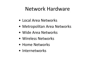
Introduction – Outline of Presentation • Communication • Requirement of Communication • Basics of Communication • Communication network • Communication Media • PLCC • VSAT • Microwave • Fiber Optics • Communication Protocols • Hardware Configuration
Requirement • Administrative • Telemetry – SCADA • Special Protection Schemes • SMART Grid Technology • Line Protection • HVDC implementation
Choice • High Reliability - Min. loss of communication; Select proper hardware etc. • High Availability - Proper selection of media; alternate routing, stand by etc. • Rapid response - Update time in specified limits. • Transparency - Compatibility with other systems. • Flexibility - Absorb future changes, additions, etc. • Maintainability - Minimum demand on maintenance
D TS SERVER ICCP COMMUNICATION SERVER ISR SERVER WORKSTATION BASED OPERATOR CONSOLE WITH TWO CRT ROUTER Scada/EMS system SCADA /EMS SERVER JUKE BOX LAN 1 FROM GPS LAN 2 NMS CONSOLE TIME SYNCH SYSTEM TERMINAL SERVER OPRATION SCHEDULING CONSOLE DUAL CFE COMMUNICATION FRONT END PROCESSOR COMMUNICATION FRONT END PROCESSOR PERIPHERALS SPLITTER TO OTHER CONTROL CENTERS VIDEO PROJECTION SYSTEM MIMIC CONTROL BOARD MODEM CHENNEL 2X64KBPS TO RTUs
Communication Network C F E Communication trough single medium P L C C COAXIALCABLE DATA SERVERS P L C C MODEM Master Station PLCC ROOM R T U P L C C PLCC COAX CABLE MODEM RTU PLCC ROOM
Monitoring and Control System Master Station Computer System Communication Channel Interface Devices A/D Converter Interface Devices A/D Converter Sensor/Transducer Relays Sensor/Transducer Relays Power systems
Analog to Digital Conversion • Sampling • According to the Nyquist 2 * fmax • Quantization and encoding
Communication Network Communication trough multiple medium medium C F E M U X Data Server F. O. / MW Master Station WIDE BAND P L C C M U X R T U P L C C PLCC COAX CABLE COAX CABLE MODEM MODEM PLCC ROOM PLCC ROOM RTU
Communication Network Communication Channel Configuration M A S T E R S T A T I O N POINT TO POINT C C SERIES C C C C C C C C SERIES STAR C C C C C C LOOP C C C C
Modulation Technique • Modulation • Amplitude modulation ( PAM ) • Frequency of carrier fiixed • Varying Amplitude • Higher Noise • Frequency modulation ( FSK ) • Frequency of the carrier varied • Amplitude not varied • Less noise • Phase modulation ( PSK ) • Phase of the carrier is varied • Amplitude not varied • Low Noise • Quadrature Amplitude Modulation ( QAM ) • Split into two signal • Added with a phase shift of 90 deg Amplitude Modulation Frequency Modulation Phase Modulation
Multiplexing • Multiplexing • Time Division Multiplexing ( TDM ) • Separate Time slot is allotted • Advantages • It uses a single links • It does not require precise carrier matching at both end of the links. • Use of capacity is high. • Easy to expand the number of users at a low cost. • No need to include identification of the traffic stream on each packet. • Frequency Division Multiplexing ( FDM ) • Separate Carrier Is allotted • Advantages • Here user can be added to the system by simply adding another pair of transmitter modulator and receiver demodulators. • FDM system support full duplex information flow which is required by most of application. • Noise problem for analog communication has lesser effect • Wave Division Multiplexing ( WDM ) • Separate Wavelength is allotted
Higher Order Multiplexing • Synchronous digital multiplexers ( SDH ) • Synchronous digital multiplexers have tributaries with the same clock frequency, and they are all synchronized to a master clock. • The basic building block is called the synchronous transport signal – level 1 ( STS – 1 ) if electrical and optical carrier level 1 ( OC – 1 ) if optical. The STS-1 has a 51.84 Mbps transmission rate and is synchronized to he network clock. The STS-1 frame structure has 90 columns and 9 rows. • Asynchronous digital multiplexers. ( PDH ) • Asynchronous digital multiplexers has tributaries which have the same nominal frequency (that means there can be a small difference from one to another), but they are not synchronized to one another. • Multiplexing techniques • Bit by Bit multiplexing/interleaving • Word by Word multiplexing / interleaving.
System Layers SDH Network Management System DWDM & STM- 16 Backbone Layer STM- 1/4 Transport Layer PDH Network Management System Primary Access Layer (< 2Mbit/s) Voice Circuits & Data Circuits FIBRE OPTIC CABLE & MICROWAVE RADIO
140 Mbit/s MUX 140 Mbit/s MUX 34 Mbit/s MUX 34 Mbit/s MUX 8 Mbit/s MUX 8 Mbit/s MUX 2 Mbit/s MUX 2 Mbit/s MUX Plesiochronous Digital Hierarchy ( PDH ) • Plesiochronous Digital Hierarchies • Primary Order - 2 Mbit/s (2,048 Kbit/s) • 30 x 64 Kbit/s Channels • Second Order - 8 Mbit/s (8,448 Kbit/s) • 4 x 2Mbit/s Tributaries • 120 x 64 Kbit/s Channels • Third Order - 34 Mbit/s (34,368 Kbit/s) • 16 x 2Mbit/s Tributaries • 480 x 64 Kbit/s Channels • Fourth Order - 140 Mbit/s (139,264 Kbit/s) • 64 x 2Mbit/s Tributaries • 1920 x 64 Kbit/s Channels
SDH Multiplexing Structure • Administrative Unit ( AU ) • Virtual Container ( VC ) • Container ( C ) • Tributary units ( TU ) • Tributary Unit Group ( TUG )
Transport Frame Formats 2Mbit/s (ITU-T G.704) • The standard bandwidth of the voice channel in a digital transmission system is 300 – 3400 kHz. • A number of input signal / channels ( typically 24 or 30 ) are combined. • Combined in a frame and Multi-frame • Input signal / Data • Frame alignment word • Service bits • Signaling bits
LDCA TAX LDCA TAX Bandwidth Capacity in 24F-OPGW Cable DARK FIBRE PAIRS FIBRE PAIRS TO BEUSED Single pair of fibres SYNCHRONOUS DIGITAL HIERARCHY (SDH) Capacity Voice channels Transport Module STM - 1 155 Mbps 1920 STM - 4 622 Mbps 7500 STM - 16 2.5 Gbps 30000 STM - 64 10.0 Gbps 120000 DWDM N * 2.5 N*2.5 Gbps N*30000 N *10 N*10 Gbps N*120000 For example 32*2.5 80 Gbps 960000 32*10 320 Gbps 3840000
Power Line Carrier Communication ( PLCC ) • HF Carrier Signal ranging from 30 kHz to 500 kHz • Mainly used for • a) Speech, • b) Tele-protection • c) Data Signal ( RTU ), • d) Meter data transfer, • e) Tele-Control • Disadvantages of PLCCs are: • a) Limited Bandwidth ( 4 kHz ), • b) Low speed of data transfer ( 1200 baud ), • c) Separate battery supply for reliable DC supply, • d) Subjected to noise – high signal to noise ratio • e) problem of frequency allocation with highly messed networks • f) Depends on physical connectivity of Power lines – network expansion problem • g) Cannot be monitored from a centralized location.
Power Line Carrier Communication ( PLCC ) • Coupling devices are used for isolation of carrier equipment from the high tension voltage system and to provide a low impedance path for carrier frequency. Generally CVTs are used with LMU. • Wave traps are used to confine the carrier signals between the two carriers equipments located at the respective substation and to provide high impedance to carrier frequency. Rated for full current.
Power Line Carrier Communication ( PLCC ) AUDIO 4KHz AUDIO BAND IS USED FOR TRANSMITTION VOICE & DATA. VOICE 0.3 –2.0 KHz DATA 2.1 – 3.4 KHZ CARRIER FREQUENCY BAND 40 KHz - 500 KHz. HIGH FREQUENCY RANGE IS USED FOR CARRIER SIGNALS SPEECH & DATA SIGNALS WILL BE TRANSMITTED IN THE 4KHz BANDWIDTH IN EACH DIRECTION OVER THE CARRIER. Eg. WITH 100/104 KHz CARRIER FREQUENCY, THE TRANSMIT SIGNALS WILL BE 100-104 KHz AND RECEIVE SIGNALS WILL BE 104-108 KHz RANGE.
Uplink 6 GHz Downlink 4 GHz HPA LNA Up Converter Down Converter C Band – 6/4GHz Ku Band -14/12GHz Ka Band – 30/20GHz Satellite Modem Satellite Modem CPE PSTN CPE PSTN Receiving Earth Station Transmitting Earth Station VSAT Communication Satellite Communication is a technology of data transmission whether one-way data broadcasting or two-way interactive using radio frequency as a medium. It consists of: • Space Segment or Satellite • Ground Segment or earth station • Antenna, • Outdoor Unit, • Inter Facility Link, • Indoor Unit and • Customer Premises Equpt. Feed Horn RFT HPA – High Power Amplifier, LNA- Low Noise Amplifier (Earth station equipment that amplifies the transmit RF signal. ) CPE – customer premises equipment ( eg. Telephone, PABX, Ethernet hub, host server, etc)
VSAT Communication Antenna diameter : 0.6m – 3.8m Traffic Capacity : 9.6kbps – 2Mbps Frequency Bands : C-band (4-6Ghz) or : Ku-Band (12-14Ghz) : Ka-Band (30/20Ghz) Use of satellite : Geo-stationary satellite (36,000km above equator) Network : Point-to-point Configuration : Point-to-multipoint
VSAT communication Technology SCPC (Single-Carrier Per Channel • point-to-point Time-division multiple access (TDMA ) • Share satellite resource on a time-slot basis Frequency Division Multiple Access ( FDMA ) • Pre-Assigned Multiple Access ( PAMA ) • Demand Assigned Multiple Access ( DAMA ) • Code Division Multiple Access ( CDMA )
Microwave Communication Microwave links provide hops of some ten or twenty kilometres. Definition : λ= C * T = C / F λ : wavelength in metres, C : speed of light in metres per second, F : frequency in Hertz, T : period in seconds C (speed of light) = 3 * 108 m/s.
Microwave Communication • Propagation Problem : • Roundness of Earth • Atmospheric Refraction • Defraction • Reflection • Due to Hydrometeors Radius of first Fresnel ellipsoid: rmax = 0.5*√ ( λ*d ) d : distance between transmitter and receiver
Microwave Communication Hot Standby Configuration ( HSB ) • Standby equipment transmits at the same time as the active equipment. • A logic circuit manages detection of a transmitter fault. This type of switching is called errored switching. • In receive mode, the two receivers receive the same signal and process it in parallel The logic circuit uses the digital signal for switching. This type of switching is called errorless switching Frequency Diversity Configuration • Frequency diversity protects signal propagation. • The system is expensive in terms of frequency bandwidth and equipment. • The signal forwarded to the terrestrial network is chosen in the same way as for the HSB configuration.
Microwave Communication Frequency Diversity Configuration • Space diversity protects propagation against fading. • The diagram shows space diversity in one transmission direction. It can be symmetric. The receiver at the top is called the main receiver, and the bottom receiver is the diversity receiver. If a diversity transmitter is installed, it must be switched off. • The signal forwarded to the terrestrial network is chosen in the same way as for the HSB configuration
Fiber Optic Communication The Ray Model The Wave Model Incidence When light travels from a less dense medium to a more dense medium i.e. when n1<n2 then the ray is refracted out of the boundary. When light travels from a more dense medium to a less dense medium i.e. when n1>n2 then the ray is reflected inside the boundary. Snell’s Law :
Fiber Optic Communication Fiber optic cable functions as a "light guide," guiding the light introduced at one end of the cable through to the other end. The light source can either be a light-emitting diode (LED) or a laser. Using a lens, the light pulses are funneled into the fiber-optic medium where they travel down the cable. • The light (near infrared) is most often are used : • 850nm for shorter distances • 1,300nm for longer distances on Multi-mode fiber • 1300nm for single-mode fiber • 1,500nm is used for longer distances.
Fiber Optic Communication Single Mode cable is a single stand of glass fiber with a diameter of 8.3 to 10 microns. Single Mode Fiber through which only one mode will propagate typically 1310 or 1550nm. Data is sent at multi-frequency (WDM Wave-Division-Multiplexing) so only one cable is needed - (single-mode on one single fiber) Multi-Mode cable has a little bit bigger diameter, with a common diameters in the 50-to-100 micron. Most applications in which Multi-mode fiber is used, 2 fibers are used (WDM is not normally used on multi-mode fiber). Light waves are dispersed into numerous paths, or modes, as they travel through the cable's core typically 850 or 1300nm.
Fiber Optic Communication Attenuation • Scattering • Due to interactions of photons with fiber medium. • Absorption ( Intrinsic + Extrinsic ) • Due to fiber itself ( Intrinsic ) • Due to impurities of water and metal, such as iron, nickel and chromium (extrinsic). • Bending and Geometrical Imperfections • Due to physical stress on fiber. • Core-cladding interface irregularities, diameter variations etc. Dispersion • Intramodal Or Chromatic Dispersion • Propagation Delay in Various Spectral Components of the Transmitted Signal. • Intermodal Dispersion • Propagation Delay Between Various Modes, Mainly in Multimode Fibres.
CIM ? Tele-protection ? DMS ?
Tele-Control Protocols • IEC 60870-5-101 protocol (from RTU to Control Center communication • IEC 60870-6-502 ( ICCP) protocol (between two Control Canters) • IEC 60870-5-103 protocol (for communication between IEDs in a Substation) • IEC 60870-5-104 protocol • MODBUS Protocol ( MFTs) • DNP 3.0 Protocol (Serial)---Master Station • DNP 3.0 Protocol (TCP/IP)---Master Station • IEC 61850 protocol (for Substation Automation) • The Present SCADA systems use • IEC 60870-5-101 • IEC 60870-6-502
IEC–60870–5-101 Physical Layer : Information bit : 8 bit Stop bit : 1 Parity bit : Even Unbalanced Request Message (User Data, Confirm Expected) Data Link Layer Standard Frame Format : FT 1.2 Maximum Frame Length : 255 bytes [P] [S] Slave Master Transmission Layer ( Station address field Length : 1 or 2 bytes ) Unbalanced Mode : Transmitted messages are categorized on two priority classes( Class 1 & Class 2 ) Balanced Mode : All the messages are sent, No categorization of Class 1 and Class 2 (Acknowledgment) Response Message [P] Network Layer : Not defined as 870-5-101 is not IP based Selection of ASDUs ASDU 1 : Single point information ASDU 2 : Single point information with time tag ASDU 3 : Double point information ASDU 4 : Double point information with time tag ASDU 9 : Measured value, Normalised value ASDU 10 : Measured value, Normalised value with time tag ASDU 11 : Measured Value, Scaled value ASDU 12 : Measured value, Scaled value with time tag ASDU 100 : Interrogation Command ASDU 103 : Clock Synchronisation Command ASDU 120 - 126 : File transfer Command (Request User Data) Application Layer The length of the header fields of the data structure are: Station address 1 or 2 byte ( User defined ) ASDU Address : 1 or 2 bytes Information Object address : 2 bytes Cause of Transmission : 1 byte [S] (Respond User Data or NACK) [P] = Primary Frame [S] = Secondary Frame
ICCP Protocol Associations An application Association needs to be established between two ICCP instances before any data exchange can take place. Associations can be Initiated, Concluded or Aborted by the ICCP instances. Bilateral Agreement and Table, Access Control A Bilateral Agreement between two control-centers (say A and B) for data access. A Bilateral Table is a digital representation of the Agreement. Data Values Data Values are objects that represent the values of control-center objects including points (Analog, Digital and Controls) or data structures. Data Sets Data Sets are ordered-lists of Data Value objects that can be created locally by an ICCP server or on request by an ICCP client Information Messages Information Message objects are used to exchange text or other data between Control Centers. Transfer Sets Transfer Set objects are used for complex data exchange schemes to transfer Data Sets (all elements or a subset of the Data set elements) etc. Devices Devices are the ICCP objects that represent controllable objects in the control center.
ICCP Protocol Conformance Blocks ICCP divides the entire ICCP functionality into 9 conformance block subsets. Implementations can declare the blocks that they provide support for, thus clearly specifying the level of ICCP supported by the implementation. Any ICCP implementation must necessarily support Block 1ca Block 1 – Basic Services Association, Data Value, Data Set, Data set transfer Block 2 – Extended Data Set Condition Monitoring Data Set Transfer Set Condition Monitoring Object Change condition monitoring, Integrity Timeout condition monitoring Block 3 – Blocked Transfers Transfer Reports with Block data Block 4 – Information Message Information Message objects, IMTransfer Set objects Start Transfer Stop Transfer Data Set Transfer Set Condition Monitoring Block 5 – Device Control Device objects Select, Operate, Get Tag, Set Tag, Timeout, Local Reset, Success, Failure Block 6 to Block 9 are not generally implemented
SLDC CPCC Sub LDC Repeater Sub Station Microwave Optical cable Underground Optical cable Monitoring Center JHARKHAND Hatiya 220/132 Bodhgaya- Lalganj Muzaffarpur ORISSA Hajipur Jeypore(PG)400/220 Manpur33 X Y Budhipadar 220/132 Kushai Colony 220KV Atri33 Fatwa Total Hops:62 New Towers:51 Patna Jayanagar Rajgir-132 Bamra Bokaro B 132 DVC U/G 220KV Bargaon33 Biharshariff 220/132 Biharshariff 400/220 Tower #313 Jamui Kutra33 Therubali Chandil 220/132 SANTHALDIH 132(WBSEB) Tarkera 220/132 220KV Akusinghi TOWER226 CTPS 132(DVC) Maithon SLDC-80 Rourkela(CS) 400/220 Kahalgaon Narendrapur Jamshedpur(CS)400/220 BIHAR Kalyaneswari Meeramandali 400/220/132 400KV Khurda 220KV TOWER #194 Barkot Mendhasal 400/220 Waria 132(DVC) 50M/SEC 47M/SEC 39M/SEC 220KV Tower#146 15 km Mejia 132(DVC) Kalipahari 132(DVC) TSTPS(CS)400 Chandaka 220/132 Durgapur(CS)400/220 Chainpal-132 7 km Farakka(CS)400/220 Kamakhyanagar-132 132KV PDT Mathkargola -33 Backup route Mankur 132-WBSEB Duburi 220/132 Bhubaneshwar132 Burdwan 132-DVC Jajpur Town 132 Naupada132 Chandikol Belmuri 132-DVC Maldah(CS) 400/220 Vidyut Bhavan NBU-132 PDT Howrah 220/132 DVC HQ Legend India Bhutan border PDT ERSCC X Y CALCUTTA Siliguri WEST BENGAL EASTERN REGION WIDEBAND TELECOMMUNICATION SYSTEM Updated as on 02/01/2020 ERSCC