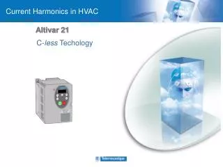
Altivar 71 Output filters Selection Guide
290 likes | 504 Vues
Producto y Versión: ATV61/71. Revisión. Fecha. Autor. Modificaciones. 1.0 2.0. 1/2011 3/2011. Sergio Núñez Núñez. Primera versión Actualización diagrama de selección y contenido. Altivar 71 Output filters Selection Guide. Centro de Competencia Técnica.

Altivar 71 Output filters Selection Guide
E N D
Presentation Transcript
Producto y Versión: ATV61/71 Revisión Fecha Autor Modificaciones 1.0 2.0 1/2011 3/2011 Sergio Núñez Núñez Primera versión Actualización diagrama de selección y contenido Altivar 71 Output filters Selection Guide Centro de Competencia Técnica
ATV 71: Output filters Selection GuideSummary • Selection Diagram • Causes of motor overvoltages • Multiplication factors • Switching frequency influences • Motors in parallel • Selection Table • Overvoltage and dv/dt limitation options • SVL overvoltage limitation function • Motor Choke. • Sinus Filter 6. Adequation of the motor
1 Output Filters Selection Diagram
4 3 5 6 2 Output Filters Selection Diagram
+ VDC bus e.g. 400 * 2 = 566V Drive output voltage (PWM) dV/dt 2 to 10kV/µS 0 V Motor current nearly sinusoidal - VDC bus Causes of motor overvoltages • The switching of the output voltage on the output of a drive by the IGBT bridge generates rapid variations in voltage (dV/dt).
dV/dt overvoltage l cable Overvoltage at the motor terminals Typically up to 2 x V bus DC ex U main =400Vac Motoring Quadrant Û = 400xSQR2x2 = 1132V Generating Quadrant (braking) Û = 790x2 = 1580V Sometimes in certain cases the overvoltage can be greater than 2 Vdc ... + Vdc - Vdc Causes of motor overvoltages • Overvoltages are generated by reflected waveforms due to dV/dt and to poor impedance matching between the motor and the motor cable. • The amplitude and the dV/dt are principally functions of the cable length and the modulation technique.
Remarks : • The dV/dt gradient is as bad for motor windings as the overvoltage itself (corona effect). • And very short wires can also be a problem because of low inductance and parasitic capacitance. Causes of motor overvoltages • Overvoltages and dV/dt can degrade the insulation of motor windings and cables. • This problem is generally above than 400V and for motors not having insulation compatible with variable speed drives (class F). • Overvoltages can be destructive with cable lengths of 20 meters or above. • The can be greater than 2Vdc in the case of PWM with short tmin (ex 2µS for 200m 4kW)
Multiplication factors • Factors to be taken into account: • If parallel cables are used, the cable lenght to be considered must be multiplied by 2, • If motors are in parallel, the cable lenght to be considered must be the sum of all motor cable lengthes. • Note: a multiplication factor can be used if the swithching frequency used is greater than the default value, but in this case, the use of output filter is not allowed.
Switching frequency influences When using “SFR” parameter for example between 4 and 8 kHz the losses increase by 1,3 in tri-phase modulation so it is necessary to dicrease the length of motor cable. Recommendation for length of motor cable in function of switching frequency. (1) These factors are theorical values. Note: a multiplication factor can be used if the swithching frequency used is greater than the default value, but in this case, the use of output filter is not allowed.
L1 L2 L3 Motors in parallel • The cable length to be considered for choosing an output filter is the sum of all the cable lengths (ex L1+L2+3L3). • Minimize the cable length (drive as close as possible to the motors).
Selection table depending on cable length Output filter recommendation according to motor cable length and previous multiplication factors.
Software overvoltage limitation function The over voltage software function (SUL) permits the limitation of the over voltage in motor terminals to 2 times the DC bus voltage. To do this, the minimum time between two PWM voltage pulses is adjustable as a function of the cable length (from 6 to 10µS) by means of the optimization paramenter “SOP”. The value of the “SOP” parameter corresponds to the attenuation time of the cable used. It is defined to prevent the superimposition of voltage refections resulting from long cable lengths. The SUL function is useful by itself below certain wiring distances. For longer cable lengths it is necessary to add additional output filters. This function is based on the elimination of shorter pulses generated in the PWM output of the drive. On the other hand, the elimination of these pulses leads to a little loss of torque estimated about 3%, that leads in a lower dynamic performance.
Software overvoltage limitation function A PWM pulse too short with respect to the time constant of the cable can lead to the superposition of 2 oscillations and generate and overvoltage > 2*V bus DC
+ 2Vdc + 2Vdc Time [s] Time [s] Software overvoltage limitation function Function not activated overvoltages greater than 2Vdc • The increase of « tmin » slightly degrades the performance but in a proportion that is acceptable with a long cable length. • The switching frequency is automatically limited to the factory setting (2.5kHz to 4kHz) SUL function activated
Software overvoltage limitation function The tables in the programmation manuals gives examples of correspondence between “SOP” parameter and the length of cable between the drive and the motor. Unshielded "GORSE" cable type H07 RN-F 4Gxx: * These tables are not available for drives of power higher than 75kW.
Software overvoltage limitation function The tables in the programmation manuals gives examples of correspondence between “SOP” parameter and the length of cable between the drive and the motor. Shielded "BELDEN" cable Type 2950x: * These tables are not available for drives of power higher than 75kW.
Software overvoltage limitation function Summary: • Principal • A PWM voltage pulse time that is very short in comparison to the period can generate an overvoltage >2 times the DC bus voltage during a positive to negative transition. • This function permits the limitation of the overvoltage to 2 times the DC bus voltage. • To do this, the minimum time between two PWM voltage pulses is adjustable as a function of the cable length (from 6 to 10µS). • This function is activated by the parameter SUL • Applications • Protection of motors against overvoltages greater than 2 Vbus DC • Cable lengths up to 150m
Maximum cable length depending on motor choke selection See catalog in order to verify the maximum cable length depending on output filter selection.
Sinus Filter Sinus filter is a low bandwidth filter with a cutoff frequency below the switching frequency (4 to 8kHz only). Sinus filter is the best solution with ATV71 to solve overvoltage at the motor terminal for long motor cable until 600m or 1000m depending on the drive power rate. Sinus filter is also the best way to reduce motor noise. For high power rates sinus filter only allows U/F motor control law and low dynamic. Vector control law in open loop is only posible until 75kW N4 or 45kW M3X voltage supply. See catalog in order to select the rigth reference. In next page you will find a table with maximum cable length depending on sinus filter reference.
Sinus Filter Maximum cable length depending on sinus filter reference: For motors in parallel, the sum of all the cable lengths must be taken into consideration. Due to capacitor between phases and ground at the output of the sinus filters, the maximum length of each cable must be divided: • by 2,5 for two motors • by 4 for three motors • by 6 for four motors
Motor choke … is much cheaper than a sinus filter has a smaller size, nearly no voltage drop, less losses Has a better peak voltage limitation against earth Allows all motor control laws (Sinus filter in HHP only allows U/f and low dynamic) No drive derating necessary (Sinus filter operates at 4kHz!) Output side of ATV61/71 Motor choke vs. Sinus filter Altivar 61/71 M1 3 VS. Motor choke
Adequation of the motor • Check is the selected motor is compatible with pre-selected drive and options • Pe-selected configuration: L < Lmax with no motor filter • Motor insulation must be compatible for the use with the variable speed drive. Refer to the next slide. • If not, it is required to add motor choke to protect the motor again dv/dt and over voltages Note: activation of the SUL function and adjustment of the parameter SOP according to the type and length of cable suppress the over voltages exceeding 2 times the bus voltage. • Pre-selected configuration: L > Lmax with motor choke and filter • The motor is protected against dV/dT • Motor protection against over-voltages can be considered by SUL function activation.
Adequation of the motor Motor protection against dV/dT • dV/dT protection : customer must be aware of the motor type intended to be used in its application, • We consider here the dV/dT on motor terminals. • Depending on this type, IEC 60034-17 defines a table for admissible dV/dT levels. • A – motors up to 500V used with a variable speed drive • B – motors up to 600V used with a variable speed drive • C – motors not specified for use with variable speed drives (IEC60034-17) Overvoltage kV Rise time µS
Adequation of the motor Motor protection against dV/dT • Independently of motor cable length, the limitation of dV/dT to 500V/µs or 1kV/µs (depending on supply voltage) is done by using a motor choke: • dV/dT limitation values with motor chokes: < 500V/µs @ 400V < 750V/µs @ 500V < 1000V/µs @ 690V • The motor choke also permits to reduce peak voltage (*). < 1000V @ 400V < 1150V @ 460V < 1800V @ 690V * (These values apply in motor mode operation). • The use of a motor choke is mandatory in case of retrofit of an installation with an old motor. • Supression of the dV/dT : • The suppression of the dV/dT on motor terminals is done by using a sinus filter.
Adequation of the motor Motor protection against over-voltage • A PWM voltage pulse time that is very short can generate an over-voltage >2 times the DC bus voltage during a positive to negative transition. • The variable speed drives integrates the SVL function, that permits the limitation of the over-voltage to 2 times the DC bus voltage. • In generative mode, the DC bus level will regulated at the DC bus braking level, that can be adapted via UBR parameter: • ATV71oooM3p: factory setting 395 V. • ATV71oooN4: factory setting 785 V. • ATV71oooS6X: factory setting 980 V. • ATV71oooY: factory setting 1127 V or 1080 V according to rating. • The activation of SVL function will limit the setting range of the switching frequency of the variable speed drive.
IEC 60034-25 • Find more information about • Motor cabling • Motor Isolation • Reduction of voltage stress • Bearing problems and causes • Motor filters • Drive principals
Make the most of your energy www.schneiderelectric.es