Download
1 / 51
651 likes | 1.56k Vues
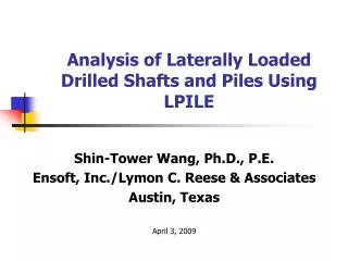
Analysis of Laterally Loaded Drilled Shafts and Piles Using LPILE. Shin-Tower Wang, Ph.D., P.E. Ensoft, Inc./Lymon C. Reese & Associates Austin, Texas April 3 , 2009. Outlines. Introduction Basic theory of the p-y curve method Numerical solution for soil-structure interaction

E N D
Analysis of Laterally Loaded Drilled Shafts and Piles Using LPILE Shin-Tower Wang, Ph.D., P.E. Ensoft, Inc./Lymon C. Reese & Associates Austin, Texas April 3, 2009
Outlines • Introduction • Basic theory of the p-y curve method • Numerical solution for soil-structure interaction • Characteristic Shape of p-y Curves • Available p-y Curve Criteria • Common Input Values • Special consideration for large-diameter piers • Effect of nonlinear EI on deflection • Special features in LPILE
Piles are used in a variety of ways to support super-structures
Drilled Shafts with Lateral Load Q M P Ultimate earth pressure (strength fully mobilized) Ultimate earth pressure (strength fully mobilized) Actual earth pressure Actual earth pressure
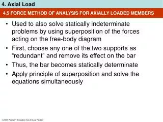
Methods of Solution • Linearly elastic solution (Poulos and Davis, 1980) emphasizes the condition of continuity although the soil cannot be characterized as a linearly elastic material. • Limit-equilibrium solution (Broms, 1965) finds the ultimate lateral load at failure, but soil-structure interaction at lesser loads is not addressed. • The p-y method with beam-column model (McClelland, Matlock, Reese, 1958-1975) has been developed extensively to take into account the soil-structure interaction and nonlinear resistance of soils. • 3-D Finite-Element method
Soil Failure Patterns Wedge Failure Plane-Strain Failure
Differential Equation EI = pile stiffness y = pile deflection x = distance along pile Px = axial load on pile and Epy= slope of secant to p-y curve at point on pile W = distributed lateral loading
Illustration of Numerical Solution Procedure V y y Epy Epy p x p
p-y Curves Developed From Static-Load Tests on24-in. Diameter Pile.
Characteristic Shape of p-y Curves c. a. Initial Linear-elastic section b. Transition from linear to nonlinear section c. Yield section into limit state or plasticity failure b. a.
Soft Clay (Matlock, 1970) Stiff Clay (1). with free water (Reese et al., 1975) (2). Without free water (Reese & Welch, 1975) Sand (Reese model & API Model) Liquefied Sand (Rollins et al., 2005) c-f Soil (Evans and Duncan*, 1982) Strong Rock (Reese & Nyman, 1978) Weak Rock (Reese, 1997) (* Concept only, not the full model) p-yCurve Criteria
Common Input Values • Effective Unit Weight • Shear Strength • Cohesion, c • Friction Angle, f • Soil Stiffness, e50 • Initial Stiffness of p-y Curve, k • Rock Properties, RQD, qu, etc.
Soft Clay Cyclic Loading Static Loading
Stiff Clay with Free Water Cyclic Loading Static Loading
Stiff Clay without Free Water Cyclic Loading Static Loading
Sand (Reese Criteria) Static & Cyclic Coefficients
Liquefied Sand (Rollins et al.) Rollins model is limited to relative densities Between 45 and 55 percent Pile diameter = 324 mm
p m pm k pk u ym pu yk yu ks y b/60 3b/80 Cemented c-f Soil Pult=Pu( f ) + Pu ( c ) Use of this p-y curve is not recommended without a load test to establish k
Vuggy Limestone p Perform proof test if deflection is in this range pu = b su Assume brittle fracture if deflection is in this range Es = 100su Es = 2000su NOT TO SCALE y 0.0004b 0.0024b
p pur A y Weak Rock • Required rock properties • Uniaxial Compressive Strength, su(from lab tests) • RQD (from field investigation records) • Rock Mass Modulus (interpreted) • krm (from lab tests or estimated) • Effective Unit Weight (from lab tests) Kir ya
Soil Layering Effects Georgiadis’ Method for Equivalent Depth (1983)
Pile-Head Conditions:Shear and Moment Qt Mt Pt Distance to Ground Surface Layer 1 Pile Length Layer 2 Layer 3 Note: Origin of Coordinate System for Pile and Soil Layers is Located at the Pile Head
Pile-Head Conditions:Displacement and Slope Qt qt yt Distance to Ground Surface Layer 1 Pile Length Layer 2 Layer 3 Note: Origin of Coordinate System for Pile and Soil Layers is Located at the Pile Head
Effect of Side Friction and Tip Resistance on Large-Diameter Piers Contact friction (maybe small) M Fs B 0.2” H Tip rotation bearing, Fb (need large mobilization) Fb Contact friction, Fs 0.05B Tip rotation bearing, Fb
Size Effect • For linear elastic portion of the p-y curves the size effect is not significant on initial k values. • For ultimate soil resistance Pu is a function of the pile diameter. • Most correlation coefficients in current p-y criteria were derived based on pile diameter of 2 ft to 4 ft.
Using service load to check deflection criteria Using factored load to check bending moment and shear
Effect of Nonlinear EI on Deflection Comparison of pile-head deflections computed for same load using elastic and nonlinear EI values. It is possible to under-predict pile-head deflections if only elastic EI values are used.
Pile Subjected to Lateral Spreading due to Liquefaction of Soils
Slope Stabilized by Drilled Shafts Fs is derived from p-y curves
Adjust the Passive Earth Pressure Not Over The Bending Capacity
Slope-Stability Analysis with Resistance from vertical piles
Main Window for LRFD Load Combos Unfactored Loads Factored Loads
Reinforcing Bar Properties Bar bundling options Warning messagefor cage spacingand percent steel
Recent Publications by Others Using LPILE • Rollins, K.M., Peterson, K.T., and Weaver, T.J.,”Lateral Load Behavior of Full-Scale Pile Group in Clay”, J. Geotech. & GeoEnviro. Eng. ASCE Vol 124, No.6, June, 1988. • Anderson, J.B., Townsend, F.C., and Grajales, B.,”Case History Evaluation of Laterally Loaded Piles”, J. Geotech. & GeoEnvir. Eng. ASCE Vol 129, No.3, March, 2003. • Davidson, W.A, McCabe, R.J., and Soydemir, C.,”Below Boston’s new Bridge”, Civil Engineering, Dec. 1998.