DAC5688 EVM Testing Setup: Signal Generation and Spectrum Analysis
This guide outlines the testing setup for the DAC5688 Evaluation Module (EVM), detailing the necessary equipment, connections, and settings. The setup includes two signal generators with 1 GHz output, a spectrum analyzer, and a power supply providing 1.8V, 3.3V, and 5V. Key connections involve SMA cables for clock signals and spectrum analysis. The equipment setup specifies clock and LO signal generator parameters, spectrum analyzer configurations, and programming steps using TSW3100 software for W-CDMA tests. Adjustments for noise correction and PLL settings are also included.

DAC5688 EVM Testing Setup: Signal Generation and Spectrum Analysis
E N D
Presentation Transcript
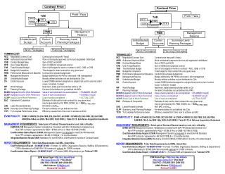
DAC5688 EVM Equipments • 2x Signal Generator with 1GHz output • 1x Spectrum analyzer • 3x rail power supply with 1.8V, 3.3V, and 5V • 4x SMA-SMA cable (2x Gore cable if possible) • 1 USB cable • 6x Banana to Banana cable • 1x TSW3100 board
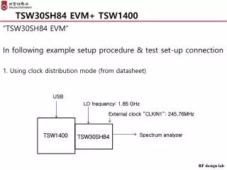
DAC5688 EVM Connections • Supply 1.8V, 3.3V, and 5V to the EVM board through J13/J14, J15/J16 and J10/J11. • Connect clock signal generator to J20 through SMA cable (Gore cable preferred). • Connect LO signal generator to J23 through SMA cable. • Connect Spectrum analyzer to J6 through SMA cable (Gore cable preferred). • Connect TSW3100 CMOS clock input (J73 on TSW3100) to J21 of DAC5688 EVM through SMA cable.
Equipment set up • Clock source sig gen = 737.28MHz with 1.6V of power. • LO source sig gen = 2030MHz with 10dBm of power. • Spectrum analyzer: • Fc = 2.17GHz • RBW=30kHz, VBW=300kHz, SWT = 2s • CP/ACP stanard = W-CDMA 3GPP FWD • Adjust reference level • Noise correction on
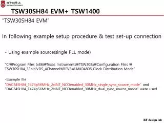
DAC5688 EVM Programming Load settings: PLL off.txt
DAC5688 • Two test plots • PLL ON setting • PLL OFF setting
Modulator out PLL ON setting PLL OFF setting