Download
1 / 20
200 likes | 428 Vues
Maximizing the Magnus Effect on Spherical Projectiles. Student Introduction: Name: Blake Loeb School: Eau Gallie High School Grade: 11 th FLVS: Hope

E N D
Maximizing the Magnus Effect on Spherical Projectiles Student Introduction: Name: Blake Loeb School: Eau Gallie High School Grade: 11th FLVS: Hope M. Blake Loeb is enrolled in the Cambridge Program and has a strong interest in Mathematics, Physics, Computer Simulations and Aerodynamics. In this year project he was able to combine these interest to create a Magnus Effect Simulator which utilized Visual Basic and Excel to perform Numerical Integration (RungeKutta 4th Order) to create a predictive model of the Magnus effect on 6mm spherical projectiles.
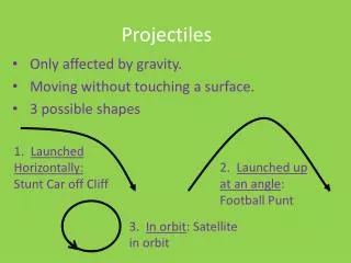
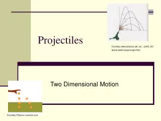
Project Introduction & Hypothesis The study of the trajectories of spherical projectiles is a key area of experimentation for classical physics as described by Sir Isaac Newton’s laws of motions. These laws however did not take into account the impact of the forces of aerodynamics (Lift & Drag). Heinrich Gustav Magnus (1802 – 1870), who investigated the effect experimentally in 1853 on rotating cylinders. As a result the lift generated by a spinning spherical projectile is now called the Magnus effect. The Magnus effect is still being research today as there are many complex factors that influence the Magnus effect. • In order to generate backspin to produce the Magnus effect spacers can be used to transfer angular velocity to the spherical projectile. • The goal of this experiment is to test different geometries of spacers and create a mathematically model of the lift generated by the Magnus effect from the experimental results. • To achieve a successful model of the Magnus force this project will cover the mathematics of applied physics for ballistics spanning hundreds of years. Source: http://pencilcricket.blogspot.com/ Hypothesis: A concave based spacer will be the most consistent way of applying pressure to a spherical projectile to cause backspin and generate optimal lift Photo taken by student researcher
Project Introduction: Hop Up Spacer Geometry - Flat, V, H and Concave Shaped Question: • Which hop up spacer geometry will create the greatest range and lift from the Magnus effect ? • What set of equations, variables. algorithms and processes can be used to create an accurate predictive model to generate the resulting spherical projectile trajectory? • Used to create backspin Included in Testing Included in Testing Included in Testing
Research and Works Cited Forces Governing Trajectory Force Equations Key Variables Gravity Velocity Drag Force Equation Lift Equation (Magnus Force) Drag & Lift Coefficient Launch Angle & Velocity System of Differential Equations
Force equations governing trajectory • What vector forces govern the trajectory of a spherical projectile? (including drag & lift) where F is the resulting force, Fgis the force fromgravity, Fdis the force from drag, Flis the force of lift from the Magnus effect and Fcis the force from all the restsuch as additional interactions due to angular momentum. For simplicity this analysis will focus on the dimensions of distance and height from these forces and will not consider cross winds or additional interacts (Fc ) Source: Physics of Paintball: Dr. Gary Dyrkacz
Key Variables Source: Flight mechanics of a Spinning Spheroid : John C. Adams, Jr., Ph.D
Gravity (W force) & Velocity • How long will it take a spherical projectile to fall 3 feet? (Time in flight without lift or air resistance) What will be the velocity be at a given point in time ? X = gt2/2 where x=distance, g=32.174 feet/sec2 and t=time vf = vi + a * t where Vfis the final velocity, Vi, is the initial velocity a is the acceleration/deacceleration with t as the time in seconds Solving for time where distance = 3 feet t=Square root (3*2/32.174) Time = .432 seconds Velocity changes in a non-linear fashion with an exponential decay Source: “Ideal Lift of a spinning sphere." Aerodynamics of a Sphere. Benson, Tom NASA - Glen Research Center, Jul 28 2008
Drag Force & Lift Equations • What are the equations governing the Drag Force? • What are the equations governingthe Lift Force? Fd is the force from drag, Cd is the experimentally determined coefficient of drag, ρ is the density of air, A is the two dimensional area of the object, which for a sphere is the same as the area of circle, π d2/4 and v is velocity of the projectile . Fl is the force from lift, Cl is the experimentally determined coefficient of lift, ρ is the density of air, A is the two dimensional area of the object, which for a sphere is the same as the area of circle, π d2/4 and v is velocity of the projectile . Source: Physics of Paintball: Dr. Gary Dyrkacz
Lift & Drag Coefficients • The Magnus effect is a function of RSR • P is pressure, R is the gas constant, T is absolute Temperature, and rho is air density of the air • CL andCD are determine experimentally Source: Flight mechanics of a Spinning Spheroid : John C. Adams, Jr., Ph.D
Resulting System of Differential Equations • These coupled differential equations are solved by numeric integration (RungeKutta) in the Magnus Effect Simulator Drag impact to V: dV/dt = -Fd g /m – g sin α Lift impact to L dL/dt =( FL g /m – g cosα)/V Launch Angle Source: Flight mechanics of a Spinning Spheroid : John C. Adams, Jr., Ph.D
Materials & Methods • Procedure:Target placement will be used to generate a projectile trajectory. Multiple tests will be executed with calculation of consistency, averages, standard deviation, and grouped by spacer geometry type.. Procedure Steps: • A mathematical model will be developed using vector and kinetic equations to predict X & Y groupings of a spherical projectile. • Air will be used to propel small spherical projectiles (6mm) down a chamber with an exchangeable spacer to produce backspin for .2g , .28g and .4g BBs • A chronograph will be used to measure exit velocity. Adjustment will be made so that for each test to make sure the propulsion system is level and targeted. This will mean that changes in X & Y groupings will be from the Magnus effect from the backspin produced. • Targets that have pressure sensitive indicators will be used to determine the X & Y groupings at regular intervals (50 feet). • The X & Y grouping information will be plugged into the mathematical model to determine lift and relative rate of backspin. • By each spacer geometry type the results will be ranked by the lift generated. Graphical and statistics based analysis will be applied. The Hypothesis that the concave based spacer will generate the most lift and consistent grouping will be tested and determine if it is correct. These results will be discussed and a conclusion will be created from this data.
Discussion: Key Variables * Response Variable
Discussion: Laminar Versus Turbulent Flow • Type of flow is dependent on the Rotational Spin Ratio (Angular Velocity (Spin)/Forward Velocity and Sphere Surface Smoothness Source: J. Hoffman and C. Johnson, Computational Turbulent Incompressible Flow, Springer 2007.
Discussion: Magnus Effect • Reverse Magnus experimentally determine to occur between 100% - 80% of initial velocity for 6 mm diameter BBs weighing .2 - .4 g Reverse Magnus Effect: Laminar flow Negative Lift Magnus Effect: Positive Lift Turbulent flow Source: Airsoft Trajectory Project
Modeling with the Magnus Effect Simulator using the described system of differential equations • Actual versus Simulation Example • Created using Excel & Visual Basic
Japa Results: Maximum Range & Height by Concave Spacer Geometry MAXIMUM VALUE Concave Spaced Geometry achieved the most range (375 Feet) and the most height (93.5 inches). Concave Spaced Geometry also had the closest grouping with the minimum standard deviation.
Conclusion • The hypothesis is correct and the concave spacer was the most consistent way of applying pressure to a spherical projectile to cause backspin and generate optimal lift (maximum range & height) • The goal of this experiment to create a mathematically model of the lift generated by the Magnus effect from the experimental results was achieved with the Magnus Effect Simulator.
Bibliography & Acknowledgments Books Butterworth, Heinemann, Aerodynamics for Engineering Students, Fifth Edition 2008 by E. L. Houghton, P. W. Carpenter. (Paperback 9780750651110) • J. Hoffman and C. Johnson, Computational Turbulent Incompressible Flow, Springer 2007 • Robins, B., Mathematical Tracts, 1 & 2. J. Nourse, London, 1761. • Robins, B., Investigation of The Difference in The Resisting Power of The Air to Swift and Slow Motion, 1742 Internet "Ideal Lift of a spinning sphere." Aerodynamics of a Sphere.Benson, Tom NASA - Glen Research Center, Jul 28 2008. Web. 28 Sep 2010. http://www.grc.nasa.gov/WWW/K-12/airplane/beach.html "Physics of Paint Ball" Lennon, Tom. Fresno University, Jul 28 August 24 2000 http://lennon.csufresno.edu/~nas31/nsa/pballIntro1.html " The Magnus Effect Equation" , Tom Cull, Staff, Clinical Sciences MR Division, Picker International Science, Jul 28 1999 http://www.madsci.org/posts/archives/1999-06/928944018.Ph.r.html> " Maximizing the Range with Newton's Method" James E. White, Calculus in Action Webbook Project Welcome to Calculus, Jul y 2004 www.maa.org/projectwelcome/calculus%20in%20action.html " Magnus Effect Experiment" , Julian Rubin, Encyclopedia of Aviation, December 2009 http://www.juliantrubin.com/encyclopedia/aviation/magnus_effect.html “Effect of Hop-Up and the Magnus Effect” The Airsoft Trajectory Project, cybersloth.org , December 2009 http://mackila.com/airsoft/ATP/03-a-01.htm “Forces Governing Trajectory” The Airsoft Trajectory Project, cybersloth.org , December 2009 http://www.physics.armstrong.edu/faculty/mullenax/research/riseball.html “Magnus effect on Spherical Projectiles” By Sanjay Mittal and Bhaskar Kumar Department of Aerospace Engineering, Indian Institute of Technology, Kanpur, UP 208 016, India, J. Fluid Mech. (2003), vol. 476, pp. 303{334. 2003 Cambridge University. Journals and Magazines Robins-Magnus Effect: A Continuing Saga.,Tapan K. Sengupta & Srikanth B. Talla Dept. of Aerospace Engineering L.J. Briggs, "Effect of spin and Speed on the Lateral Deflection (Curve) of a ball; and the Magnus Effect for Smooth Spheres," American Journal of Physics V 27, pp. 589-596 (1959). Journal of Fluid Mechanics The Magnus or Robins effect on rotating spheres Journal of Fluid Mechanics (1971), 47: 437-447 Cambridge University Press Newton, I. (1672), New theory of light and colours. Philosophical Transactions of the Royal Society London, 1, 678-688. • Acknowledgments • My thanks to the staff of SOCOM Airsoft Arena, 210 NW 13th Street, Ocala, FL 34475, for allowing me to perform this testing at their facility.