Download
1 / 28
280 likes | 391 Vues
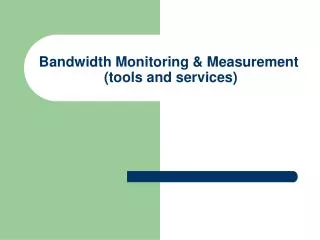
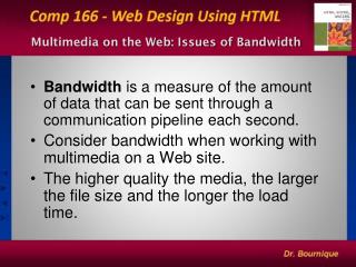
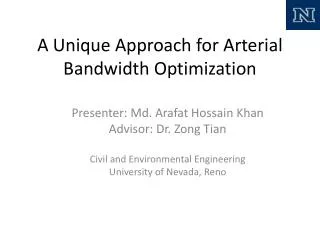
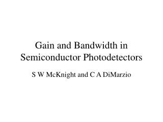
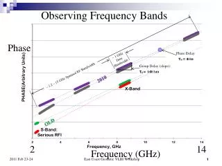
Observing Frequency Bands. Phase. ~ 2.2 – 15 GHz Spanned RF Bandwidth. OLD. 2. 14. Frequency (GHz). 1. Feed and LNAs cooled to ~20K Both senses of linear polarization used. RF filter phase/noise cal. Antenna. Control room.

E N D
Observing Frequency Bands Phase ~ 2.2 – 15 GHz Spanned RF Bandwidth OLD 2 14 Frequency (GHz) East Coast Geodetic VLBI Workshop 1
Feed and LNAs cooled to ~20K Both senses of linear polarization used RF filter phase/noise cal Antenna Control room Odd channels from each pol’n for one band output to each Mk5B+. 2 gigabits/sec recorded on each Mk5B+. Total data rate: 8 gbps East Coast Geodetic VLBI Workshop
Broadband-S/X differences S/XVLBI2010 # of bands 2 4 # of recorders 1 4 (initially) Polarizations 1 circular 2 linear Observables* one group delay two phase delays** Ionosphere from S/X comb estimated w/delays Source structure not used needed for phases * assumes rates not used ** correlated because of atmosphere, source position, etc East Coast Geodetic VLBI Workshop 3
The End East Coast Geodetic VLBI Workshop
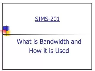
VLBI2010 Project New geodetic system based on smaller (~12m), fast slewing antennas with four bands of RF between 2 and 14 GHz. Proof-of-concept equipment was installed on two existing antennas and observations taken Westford 18m antenna, Massachusetts MV-3 5m antenna, Washington, D.C. New 12m antenna installed at Goddard Space Flight Center Will use new Eleven feed, next generation Digital Back Ends, and Mark5C recorders (January) Correlation on DiFX software correlator being implemented at Haystack (joint astronomy and geodesy) East Coast Geodetic VLBI Workshop
The End East Coast Geodetic VLBI Workshop
VLBI2010 Project New geodetic system based on smaller (~12m), fast slewing antennas with four bands of RF between 2 and 14 GHz. Proof-of-concept equipment was installed on two existing antennas and observations taken Westford 18m antenna, Massachusetts MV-3 5m antenna, Washington, D.C. New 12m antenna installed at Goddard Space Flight Center Will use new Eleven feed, next generation Digital Back Ends, and Mark5C recorders (January) Correlation on DiFX software correlator being implemented at Haystack (joint astronomy and geodesy) East Coast Geodetic VLBI Workshop
System components - 1 Broadband (2-12 GHz) feed Low noise broadband amplifiers Phase and noise calibration system Flexible local oscillator for band selection (4) Digital backend (4) High data rate recorder (4) East Coast Geodetic VLBI Workshop
Broadband Back-End Hardware 8 gigabit/sec LOs andback end ORCA Box DBEs UDCs Mark5B+ East Coast Geodetic VLBI Workshop
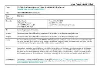
Figure C. 12m antenna at Goddard Geophysical and Astronomical Observatory, Greenbelt, Marylandbb East Coast Geodetic VLBI Workshop
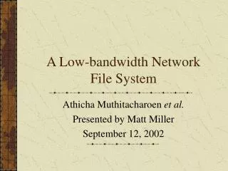
Figure D. The Eleven feed: 2-12 GHz dual linear polarization; frequency independent phase center and beam shape. East Coast Geodetic VLBI Workshop
VLBI2010 Proof-of-Concept Demonstration Arthur Niell and The Broadband Development Team East Coast Geodetic VLBI Workshop 12
Broadband Delay Team Bruce Whittier1, Mike Titus1, Jason SooHoo1, Dan Smythe1, Alan Rogers1, Jay Redmond2, Mike Poirier1, Arthur Niell1, Chuck Kodak3, Alan Hinton1, Ed Himwich3, Skip Gordon2, Mark Evangelista2, Irv Diegel2, Brian Corey1, Tom Clark3, Roger Cappallo1, and Chris Beaudoin1 1 MIT Haystack Observatory 2 HTSI, Inc 3 GSFC/NVI Special thanks to Sandy Weinreb and Hamdi Mani East Coast Geodetic VLBI Workshop
Status - 1 Proof-of-concept equipment was installed on two existing antennas Westford 18m antenna, Massachusetts MV-3 5m antenna, Washington, D.C. Phase-calibrated observations obtained Polarization test on 4C39.25 Switching between 3C273 and 3C279 Correlation/post-correlation Correlated on Mk4 and DiFX East Coast Geodetic VLBI Workshop
Status - 2 Patriot 12m antenna Antenna assembled near 5m at GGAO, Wash, D.C. Controls, cabling, and receiver equipment not on Dewar with new feed/LNAs ready for installation Will use same control room as 5m antenna RDBE digital back end and Mark5C recorder Fringes have been obtained on Westford-MV3 Operational versions are being tested Commercial version of RDBE on order (8 needed) East Coast Geodetic VLBI Workshop
Status - 3 DiFX software correlator Phase cal implementation almost complete Control scripting and output path not complete Post-correlation fringe fitting Delay coherently estimated in each polarization Polarization combination and ionosphere estimation not implemented East Coast Geodetic VLBI Workshop
Contiguous bands 6.4 GHz – 8.4 Ghz No phase cal With phase cal East Coast Geodetic VLBI Workshop
Polarization test East Coast Geodetic VLBI Workshop
System Components - 2 Current (PofC) Next (Prototype) Feed Lindgren Eleven RF amplif’n 2 LNAs 8 LNAs Calibration Phase/noise same Flexible LO UpDown Conv same Digital Back End DBE1(iBOB) RDBE (ROACH) Recorder Mk5B+ Mk5C Correlator Mk4 (hardware) DiFX (software) East Coast Geodetic VLBI Workshop 19
MV-3 5M Antenna @ GGAO Broad Band LNAs & Feed in Dewar MV3 East Coast Geodetic VLBI Workshop 20
Next - 1 12m antenna Add cabling and power Install cryo-system for cooling receiver Install Dewar with feed and LNAs; phase and noise calibration box; amplifier/fiber-xmtr box Awaiting testing and adjustment of antenna servo control by Patriot Awaiting permission to clear trees for 5° horizon mask East Coast Geodetic VLBI Workshop
Next - 2 Control room/trailer Replace DBE1/Mark5B+s with RDBE/Mark5Cs Upgrade networking Analysis Combining multiple bands, polarizations, pcal, and ionosphere estimation in fourfit VLBI broadband fringes to the 12m in 2010 !! East Coast Geodetic VLBI Workshop
The End East Coast Geodetic VLBI Workshop
Proof-of-Concept Development Goal: demonstrate four-band phase delay measurement Install the proof-of-concept equipment on two existing antennas Westford 18m antenna, Massachusetts MV-3 5m antenna, Washington, D.C. Develop improved components as prototype for operational system Install the prototype equipment on a 12m antenna that meets the WG3 requirements East Coast Geodetic VLBI Workshop
Proof of Concept System New equipment Commercial broadband feed and LNAs Cover entire frequency range in one feed Flexible frequency converter (UDC) Choose best frequencies Avoid RFI New phase cal generator Digital back end (DBE) High data rate recorder East Coast Geodetic VLBI Workshop
Feed and LNAs cooled to ~20K Both senses of linear polarization used RF filter phase/noise cal Antenna Control room Odd channels from each pol’n for one band output to each Mk5B+. 2 gigabits/sec recorded on each Mk5B+. Total data rate: 8 gbps East Coast Geodetic VLBI Workshop
Impact on geodetic VLBI Dual linear polarization Intrinsic to broadband feed Very high data record rate Per polarization in each band: 1 Gbps Per band: 2 Gbps Total data rate : 8 Gbps East Coast Geodetic VLBI Workshop
The End East Coast Geodetic VLBI Workshop