Module-3
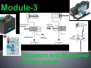
Actuators and directional control valves. Module-3. Module Objectives. Differentiate between the main types of directional control valves. Demonstrate the function and uses of 3/2 way valve, push button actuated. Demonstrate the function and uses of 3/2 way valve, roller lever actuated.

Module-3
E N D
Presentation Transcript
Actuators and directional control valves Module-3
Module Objectives • Differentiate between the main types of directional control valves. • Demonstrate the function and uses of 3/2 way valve, push button actuated. • Demonstrate the function and uses of 3/2 way valve, roller lever actuated. • Explain the function and uses of 5/2 way valve, selector valve. • Explain the function and uses of 5/2 way valve, pilot valves. • Explain the main types of pneumatic actuators.
Module Objectives cont’d… • Explain the function of the single acting cylinder and the double acting cylinder. 8. Describe the main types of controlling single acting cylinder and double acting cylinders 9. Draw the required circuit diagram as per the given specifications. 10. Use the FluidSIM software to build and simulate a pneumatic circuits that contain DCV, single and double acting cylinders. 11. Safely use the pneumatic Festo trainers to build different circuits. 12. Build a pnueumatic circuit using DCV, single and double acting cylinders on the Festo trainer and check their operation
Introduction to Directional Control Valves • Directional control valves are devices which influence the path taken by an air stream. • The directional control valve is represented by two numbers. • The first number represents the number of ports, and the second number represents the number of Positions. DCV Ports and positions
Types of Directional Control Valves 3/2 WAY (a) pressure port (1) is blocked A) 3/2 way DCV-push button - Normally Closed (N/C) Function: • The DCV allows the air flow into different paths from one or more sources. Way of operation: • A 3/2-way valve has 3 ports and 2 switching positions. • Normally closed means that compressed air CANNOT flow initially through the valve. • When the pushbutton is actuated the valve is opened, thus allowing the air to flow from port (1) to port (2). (b) 3/2 way DCV push button (NC) (before actuation) Fig. 3.3: 3/2 way DCV push button (N/C) after actuation
Types of Directional Control Valves 3/2 WAY A) 3/2 way DCV-push button - Normally Closed (N/C) Un-actuated • In normally closed 3/2 way valve, a spring-loaded disk seal blocks the air flow from the air supply port (1) to the working port (2). • The working port (2) is connected with exhaust port (3) as shown in Fig on the right. (b) 3/2 way DCV push button (NC) (before actuation
Types of Directional Control Valves 3/2 WAY A) 3/2 way DCV-push button - Normally Closed (N/C) Actuated • Allows the flow from port (1) to port (2) and blocking the exhaust port (3) . • ISO symbol of 3/2 way valve normally closed (N/C) and spring reset. • Picture of the valve.
Types of Directional Control Valves 3/2 WAY B) 3/2-DCV - push button - Normally Open (N/O) Way of operation: • Normally open means that compressed air flows through the valve. • When the push button is actuated the valve is closed, thus stopping the air to flow from port (1) to port (2). (a) 3/2 way directional control valve N/O
Types of Directional Control Valves 3/2 WAY B) 3/2-DCV - push button - Normally Open (N/O) Un-actuated • In the normally open 3/2 way valve, a spring loaded disk blocks exhaust port (3). • The air supply port (1) is connected to the working port (2). Actuated • Allows the flow from port (2) to port (3) and blocking the supply air port (1). • Fig. (3.5.b) to the left shows the ISO symbol of 3/2 way valve Normally open (N/O)and spring reset, and Fig. 5.5.c shows the picture of the valve. ISO symbol of 3/2 way DCV push button (NO) Picture of 3/2 way DCV push button (N/O).
Types of Directional Control Valves 3/2 WAY C) 3/2 Way-DCV- Roller Lever Valve - Normally closed (N/C) • One of the most important types of valve actuation. • It is generally known as pneumatic limit switch. Symbol and Construction ISO symbol Picture of the roller lever valve Construction
Types of Directional Control Valves 3/2 WAY C) 3/2 Way-DCV- Roller Lever Valve - Normally closed (N/C) Way of operation: • This valve is actuated by pressing the roller lever e.g. by means of cylinder trip cam. • The valve is returned to the normal position via return spring after releasing the roller lever.
Types of Directional Control Valves 3/2 WAY D) 3/2 way, DCV selector valve • The way of operation of the selector valve is the same as the 3/2 DCV push button. • The only difference that the selector valve is keeping the last position active either it is NO or NC. • Fig. 3.7 shows the picture and the ISO symbol of the 3/2 way, selector valve.
Types of Directional Control Valves 5/2 WAY **** 5/2 way Directional Control Valve • This valve contains 5 ports and 2 positions. • The 5/2 DCV could be actuated manually or by using pressure actuation (single pilot and double pilot), or by electrical actuation (solenoid).
Types of Directional Control Valves 5/2 WAY Before actuation • When the 5/2-way valve is not actuated, the flow will be from port (1) to port (2) while the exhaust will be from port (4) to port (5) After actuation • After operating the valve by any method, the valve will be shifted to the other position and in this case, the flow will be from port (1) to port (4) while the exhaust will be from port (2) to port (3) (a) Initial position (before actuation) (b) Second position (after actuation) ISO symbol of 5/2 way valve
Types of Directional Control Valves 5/2 WAY 1) 5/2 way selector valve • This valve is used for manual operation. • You can control the valve by selector switch. • It is used in simple applications. • The valve keeps the last position active as the 3/2 way selector.
Types of Directional Control Valves 5/2 WAY B) 5/2 way single pilot valve • This valve is used for automatic operation • You can control the valve by a pneumatic signal and a spring return.
Types of Directional Control Valves 5/2 WAY C) 5/2 way double pilot valve • This valve is used for automatic operation • You can control the valve by two pneumatic signals • The valve keeps the last position after removing the applied signal, and it is sometimes called memory valve.
Valve Actuators The pneumatic directional control valves can be actuated (operated) in several ways such as follows: 1. Manual Actuators 2. Mechanical Actuators 3. Electrical Actuators
Valve Actuators 1. Manual actuators 2. Mechanical actuators 3. Electrical actuators4.Electrical actuators MANUAL PUSH BUTTON FOOT PEDAL ROLLER IDLE RETURN ROLLER SOLENOID PNEUMATIC – PRESSURE
Pneumatics Actuators • They are used to produce the required forces in the pneumatic systems. • The pneumatic actuators are divided into: Linear actuators – Single acting cylinder – Double acting cylinder Rotary actuators – Air motors
Single Acting Cylinder • Single acting cylinder is an output device. • Its function: • To convert the pressure energy to mechanical energy (linear force in one direction only).
Circuit Control for a Single Acting Cylinder • The piston rod of a single-acting cylinder is to advance when a push button is operated. • When the push button is released, the piston is to automatically return to the initial position. • A 3/2-way valve controls the single-acting cylinder. • The valve switches from the • initial position into the flow position, when the push-button actuator is pressed.
Double Acting Cylinder • Double acting cylinder is an output device. • Its function to convert the pressure energy to mechanical energy (linear force and motion in two directions). . Note: The force produced by the piston during the advance stroke is greater than the force produced during the return stroke due to the area difference between the two sides of the piston.
Circuit Control for a Double Acting Cylinder • The piston rod of a double-acting cylinder is to advance when a 5/2 selector valve is operated and to return to the initial position when the selector switch is back to the normal position. • The double-acting cylinder can carry out work in both directions of motion, due to the full air supply pressure being available for extension and retraction. A direct control circuit of a double acting cylinder is shown in Fig. 3.15 to the left.
Applications of a double acting cylinder include 1. Opening and closing doors 2. Taking items off conveyor belts and putting items on conveyor belts. 3. Lifting and moving packages around. 4. Presses and punches.
How to control pneumatic cylinders? There are two ways to control pneumatic cylinders: 1- Direct control 2- Indirect control
Direct Control of a Pneumatic Cylinder • The simplest level of control for the single or double acting cylinder involves direct control signals. • The cylinder is actuated directly via a manually or mechanically actuated valve, without any intermediate a switching of additional directional control valves. • If the port sizes and the flow values of the valve are too large, the operating forces required may be too great for direct manual operation. Reference values for limits of direct cylinder control: Cylinder with piston diameter smaller than 40 mm Valves with connection sizes smaller than 1/4"
Indirect Control of a Pneumatic Cylinder • Cylinders with a large piston diameter have a high air requirement. • A control element with high nominal flow rate must be used to actuate these. • If the force should prove too high for a manual actuation of the valve, then an indirect actuation should be constructed, whereby a signal is generated via a second smaller valve, which will provide the force necessary to switch the control element.
Safety in the Pneumatics Lab The following safety precautions should be strictly followed in the pneumatics lab. 1. Wear the safety gear before starting any practical work on the trainer. 2. The working pressure shouldn’t exceed 6 bar, that could be achieved by adjusting the pressure regulator in the air service unit to 6 bar. 3. Securely plug in pneumatic devices. 4. Keep piston rod travel free. 5. Check all connections before connecting the compressed air. 6. Do not exceed the maximum pressure. 7. Do not completely unscrew the regulating screw. 8. Tighten each locknut after setting the regulating screw. 9. Never tighten the regulating screw with force. 10. Never operate roller by hands. 11. Connect the compressed air supply only when you complete all connections.
References For further reading, you can use the following links: 1- www.Fest-didactic.com 2- http://www.eng2all.com/vb/t28932.html 3- http://www.logiclab.hu/lesson.php?fe=2 11. Supplementary recourses 1. Pneumatics video from Festo. 2. FluidSIM software. 12. References 1- Festo manuals and workbook TP101 2- Festo manuals and textbook TP101
Classwork Do the worksheet at the end of module 3 in class
Home work Don’t forget to submit homework 3 next class