Download

1 / 27
380 likes | 676 Vues
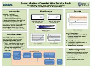
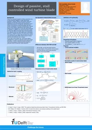
Explore the science behind wind turbine blade design, materials, construction, and performance factors. Learn about blade composition, lift and drag forces, airfoil shapes, twist and taper effects, and optimal tip-speed ratios for efficiency. Discover pitch control mechanisms and manufacturing processes for creating efficient wind turbine blades.

E N D
Wind Turbine Blade Design Joseph Rand The Kidwind Project joe@kidwind.org 877-917-0079
Calculation of Wind Power • Power in the wind • Effect of swept area, A • Effect of wind speed, V • Effect of air density, Power in the Wind = ½ρAV3 R Swept Area: A = πR2 Area of the circle swept by the rotor (m2).
Many Different Rotors… KidWind Project | www.kidwind.org
Number of Blades – One • Rotor must move more rapidly to capture same amount of wind • Gearbox ratio reduced • Added weight of counterbalance negates some benefits of lighter design • Higher speed means more noise, visual, and wildlife impacts • Blades easier to install because entire rotor can be assembled on ground • Captures 10% less energy than two blade design • Ultimately provide no cost savings
Number of Blades - Two • Advantages & disadvantages similar to one blade • Need teetering hub and or shock absorbers because of gyroscopic imbalances • Capture 5% less energy than three blade designs
Number of Blades - Three • Balance of gyroscopic forces • Slower rotation • increases gearbox & transmission costs • More aesthetic, less noise, fewer bird strikes
Blade Composition Wood Wood • Strong, light weight, cheap, abundant, flexible • Popular on do-it yourself turbines • Solid plank • Laminates • Veneers • Composites
Blade CompositionMetal • Steel • Heavy & expensive • Aluminum • Lighter-weight and easy to work with • Expensive • Subject to metal fatigue
Blade ConstructionFiberglass • Lightweight, strong, inexpensive, good fatigue characteristics • Variety of manufacturing processes • Cloth over frame • Pultrusion • Filament winding to produce spars • Most modern large turbines use fiberglass
Lift & Drag Forces • The Lift Force is perpendicular to the direction of motion. We want to make this force BIG. • The Drag Force is parallel to the direction of motion. We want to make this force small. α = low α = medium <10 degrees α = High Stall!!
Airfoil Shape Just like the wings of an airplane, wind turbine blades use the airfoil shape to create lift and maximize efficiency. The Bernoulli Effect
Lift/Drag Forces Experienced by Turbine Blades KidWind Project | www.kidwind.org
Twist & Taper • Speed through the air of a point on the blade changes with distance from hub • Therefore, tip speed ratio varies as well • To optimize angle of attack all along blade, it must twist from root to tip Fastest Faster Fast
ΩR V TSR = Tip-Speed Ratio ΩR R Tip-speed ratio is the ratio of the speed of the rotating blade tip to the speed of the free stream wind. There is an optimum angle of attack which creates the highest lift to drag ratio. Because angle of attack is dependant on wind speed, there is an optimum tip-speed ratio Where, Ω = rotational speed in radians /sec R = Rotor Radius V = Wind “Free Stream” Velocity
Performance Over Range of Tip Speed Ratios • Power Coefficient Varies with Tip Speed Ratio • Characterized by Cp vs Tip Speed Ratio Curve
All wind power cannot be captured by rotor or air would be completely still behind rotor and not allow more wind to pass through. Theoretical limit of rotor efficiency is 59% Most modern wind turbines are in the 35 – 45% range Betz Limit
Rotor Solidity Solidity is the ratio of total rotor planform area to total swept area Low solidity (0.10) = high speed, low torque High solidity (>0.80) = low speed, high torque R a A Solidity = 3a/A
Pitch Control Mechanisms KidWind Project | www.kidwind.org
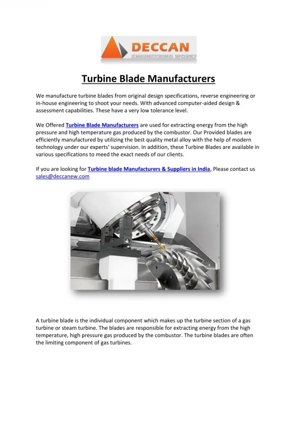
Manufacturing Blades The blade mold (left) is lined with layers of fiberglass, then injected with epoxy resin. To enhance stiffness, a layer of wood is placed between the fiberglass layers. The two molds are joined and adhered together using a special liquid epoxy, which evenly joins the two sides of the blade. Finally, the whole mold is baked like a cake! 8 hours at 70 degrees C.
Manufacturing Blades Before delivery, samples of the rotor blades have to go through a variety of static and dynamic tests. First, they are subjected to 1.3 times the maximum operating load. To simulate 20 years of material fatigue, the blades are then mounted on special test beds and made to vibrate around two million times, before the endurance of the material is again tested with a final static test. The blades are painted white, then shipped to wind farms all over the world.
Advanced Classroom Blades Cardboard Tube for twisted blades Airfoil Blades
Wind Turbine Blade Challenge • Students perform experiments and design different wind turbine blades • Use simple wind turbine models • Test one variable while holding others constant • Record performance with a multimeter or other load device • Goals: Produce the most voltage, pump the most water, lift the most weight • Minimize Drag • Maximize LIFT • Harness the POWER of the wind!
Questions? Joe Rand KidWind Project joe@kidwind.org