Download

1 / 1
10 likes | 169 Vues
THE HUYGENS MISSION

E N D
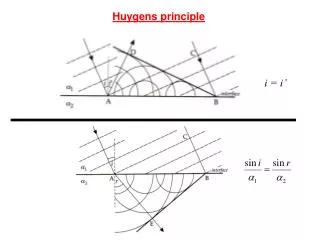
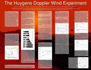
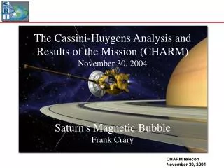
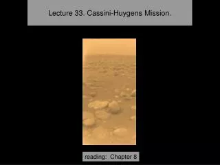
THE HUYGENS MISSION The Huygens probe is the ESA’s main contribution to the Cassini/Huygens mission, carried out jointly by NASA, ESA and ASI. It was designed to descend into the atmosphere of Titan on January 14, 2005, providing surface images and scientific data to study the ground and the atmosphere of Saturn’s largest moon THE SM2 TEST FLIGHT Two years before the launch of the Cassini/Huygens spacecraft, in May 1995, a test probe called SM2 (Special Model 2) was dropped in the Earth’s atmosphere from the balloon launch site of Kiruna, Sweden, to verify proper operation during the descent and especially the parachute deployments sequence. • 1. Huygens mission spin profile (cfr. M.Pérez et al., “Huygens attitude reconstruction based on engineering parameters”) • ~ 7.5 rpm through entry phase (spin induced at Cassini ejection) • Spin annihilation at direction reversal SPIN RATE • 2. SM2 test flight spin rate ( X-axis gyroscope ) • Spin movement starts after front shield release (spin vanes active) • Constant direction under main chute and stabilizer chute, no annihilation • Oscillations under recovery chute (no swivel suspension cable acts as torsional spring) around -1.4 rpm ( = parachute spin rate?) • FREQUENCY DOMAIN COMPARISON • SM2 Z-axis accelerometer spectrum • Huygens RASU spectrum • Similarities: • Calm descent under main chute, noisy under stabilizer chute • Dominant horizontal frequency lines: • Differences: • Varying line decreasing from 1 Hz to 0.6 Hz under stabilizer on Huygens, absent on SM2 • Progressive damping of oscillations under stabilizer on Huygens, no damping on SM2 • ( but SM2 stabilizer phase much shorter) • SM2 gyroscopes confirm that the SM2 frequency lines are reflecting attitude motions • Frequency comparison: • fSM2 / fHuygens = 2.77 (Main) ; 2.6 (Stabilizer) • ~ ( g Earth / g Titan )1/2= 2.7 • It is likely that the same type of movement was observed for the SM2 test flight and for the Huygens mission • Still to be explained: • - parachute influence • - presence of decreasing frequency line on RASU Pilot & Main Chute Deployments Stabilizer Chute Deployment Recovery Chute Deployment Landing Stabilizer Chute Main Chute Under Balloon & Gondola Main Chute Stabilizer Chute Recovery Chute Front Shield Release PROBE CHARACTERISTICS SIMULATIONS to fit CASU / RASU Based on the identified frequencies of about 1 Hz -- which should correspond to attitude motions according to the SM2 comparison. The effect on the Huygens accelerometers of pendulum-like and coning-like probe motions was simulated and compared to the mission measurements. Variables: • Amplitude q • Fix point height l [ discarding what happens above l ] Results: • Most plausible fixed point: ~ 10 cmabove accelerometers • Most plausible aperture angles: - Main chute: 0 – 4° - Beginning stabilizer chute: 4 – 9° - End stabilizer chute: 1 – 5° SPIN DIRECTION SM2 Acc. and Gyro axes definitions After the spin direction anomaly was confirmed on Huygens, the SM2 spin direction was also investigated 1. According to X-gyroscope, SM2 was spinning clockwise as seen from above (see positive gyroscope measurement and axes definitions on the right) 2. On video recording, sun ray is moving clockwise (up-looking) probe is moving counterclockwise (up-looking), which is clockwise seen from above, confirming the result: Spin direction anomaly present on SM2 Check of spin vane orientation on the SM2 probe: seems to induce counterclockwise torque SM2 up-looking video camera – Main chute release Consecutive pictures a) – d) cover an interval of about 4s FLIGHT CHARACTERISTICS ~ COMPARISON OF THE HUYGENS MISSION AND THE SM2 TEST FLIGHT FOR HUYGENS ATTITUDE RECONSTRUCTION ABSTRACT A. Sarlette(1), M. Pérez-Ayúcar, O. Witasse, J.-P. Lebreton Planetary Missions Division, Research and Scientific Support Department, ESTEC-ESA, Noordwijk, The Netherlands. (1)Stagiaire from February 1 to April 29; student at Liège University, Belgium Email: alain.sarlette@student.ulg.ac.be, mperez@rssd.esa.int, owitasse@rssd.esa.int, jplebret@rssd.esa.int The Huygens probe is the ESA’s main contribution to the Cassini/Huygens mission, carried out jointly by NASA, ESA and ASI. It was designed to descend into the atmosphere of Titan on January 14, 2005, providing surface images and scientific data to study the ground and the atmosphere of Saturn’s largest moon. In the framework of the reconstruction of the probe’s motions during the descent based on the engineering data, additional information was needed to investigate the attitude and an anomaly in the spin direction. Two years before the launch of the Cassini/Huygens spacecraft, in May 1995, a test probe called SM2 (Special Model 2) was dropped in the Earth’s atmosphere from the balloon launch site of Kiruna, Sweden, to verify proper operation during the descent and especially the parachute deployments sequence. It featured a flight standard structure and DCSS (Descent Control SubSystem) and, unlike the Huygens probe, was fully instrumented to monitor the orientation of the descent module (3-axes accelerometers and gyroscopes). On this poster, we describe how a comparison between the SM2 test flight and the Huygens mission provides some information about the Huygens probe’s behaviour. After briefly discussing the spin direction, we focus on the tip and tilt. The final conclusions of this comparison are still of qualitative nature, but the results are a starting point for better interpretation of the engineering data in terms of attitude to derive the probe’s orientation.