Introduction to Sequential Logic in Digital Systems
220 likes | 345 Vues
In this lecture, we explore the fundamental principles of sequential logic, covering key concepts like latches, flip-flops, and state machines. We'll discuss how sequential systems store memory and utilize feedback in design, distinguishing them from combinational systems that are memoryless. Important topics include timing diagrams, synchronous and asynchronous inputs, and the associated challenges like metastability. A real-world application is illustrated through a door combination lock example, emphasizing design steps and state representation in finite state machines. Assignments and updates regarding the course schedule are also provided.

Introduction to Sequential Logic in Digital Systems
E N D
Presentation Transcript
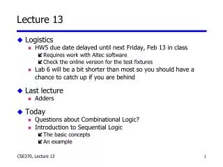
Lecture 13 • Logistics • HW5 due date delayed until next Friday, Feb 13 in class • Requires work with Altec software • Check the online version for the test fixtures • Lab 6 will be a bit shorter than most so you should have a chance to catch up if you are behind • Last lecture • Adders • Today • Questions about Combinational Logic? • Introduction to Sequential Logic • The basic concepts • An example
We've finished combinational logic... • Negative numbers in binary • Truth tables • Basic logic gates • Schematic diagrams • Minterm and maxterm expansions (canonical, minimized) • de Morgan's theorem • AND/OR to NAND/NOR logic conversion • K-maps, logic minimization, don't cares • Multiplexers/demultiplexers • PLAs/PALs • ROMs • Multi-level logics • Timing diagrams • Hazards • Adders Questions ? We had no way to store memory: When the input changed, the output changed Next: Sequential logic can store memory…
Sequential Logic (next 5 weeks!) • We learn the details • Latches, flip-flops, registers (storage) • Shift registers, counters (we can count now!) • State machines (when we can store, we have states) • Moore and Mealy machines (types of state machines) • Timing and timing diagrams • timing more important than for combinational logic • Synchronous and asynchronous inputs • Metastability (problem!)
The “WHY” slide • Learning sequential logic • Having the ability to hold memory is important. If you couldn’t use your prior knowledge stored in the memory, you wouldn’t be very smart (and same goes for a computer).
A C B clock Sequential versus combinational Apply fixed inputs A, B When the clock ticks, the output becomes available Observe C Wait for another clock tick Observe C again Combinational: C will stay the same Sequential: C may be different
Inputs Outputs System Inputs Outputs System Feedback Sequential versus combinational • Combinational systems are memoryless • Outputs depend only on the present inputs • Sequential systems have memory • Outputs depend on the present and the previous inputs
A C B clock Synchronous sequential systems • Memory holds a system’s state • Changes in state occur at specific times • A periodic signal times or clocks the state changes • The clock period is the time between state changes State changes occur at rising edge of clock pulsewidth duty cycle = pulsewidth/period (here it is 50%) clock period
Steady-state abstraction • Outputs retain their settledvalues • The clock period must be long enough for all voltages to settle to a steady state before the next state change A C B clock Clock hides transient behavior clock C Settled value
What did I just say about sequential logic? • Has clock (mostly - always for us) • Synchronous = clocked • Exception: Asynchronous circuits • Has state • State = memory • Employs feedback • Assumes steady-statesignals • Signals are valid after they have settled • State elements hold their settled output values
Example: A sequential system • Door combination lock • Enter three numbers in sequence and the door opens • As each new number is entered, press ‘new’ (like `enter’) • If there is an error the lock must be reset • After the door opens the lock must be reset • Inputs: Sequence of numbers, reset, new • Outputs: Door open/close • Memory: Must remember the combination We will go through the motion of designing a real system We will teach details of “how” to do these steps in the next few weeks
new value reset clock open/closed Understand the problem • Consider I/O and unknowns • How many bits per input? • How many inputs in sequence? • How do we know a new input is entered? • How do we represent the system states?
new value reset clock open/closed Implement using sequential logic • Behavior • Clock tells us when to look at inputs • After inputs have settled • Sequential: Enter sequence of numbers • Sequential: Remember if error occurred • A diagram may be helpful • Assume synchronous inputs • State sequence • Enter 3 numbers serially • Remember if error occurred • All states have outputs • Lock open or closed
States: 5 Each state has outputs Outputs: open/closed Inputs: reset, new, results of comparisons Assume synchronous inputs ERR closed C1!= value& new C2!= value& new C3!= value& new S1 S2 S3 OPEN reset closed closed closed open C1== value& new C2== value& new C3== value& new not new not new not new A diagram (called finite-state diagram) We use state diagrams to represent sequential logic System transitions between finite numbers of states Shorthand: implies arrow from every state labeled ‘reset’
Data path Stores combination Compares inputs with combination Control Finite state-machine controller Control for data path State changes clocked new reset C1 C2 C3 4 4 4 mux control multiplexer 4 controller clock value comparator equal 4 open/closed Separate data path and control
Refine state diagram to include internal structure Generate state table ERR closed not equal& new not equal& new not equal& new S1 S2 S3 OPEN closed mux=C1 closed mux=C2 closed mux=C3 reset open equal& new equal& new equal& new not new not new not new Refine diagram; generate state table next reset new equal state state mux open/closed1 – – – S1 C1 closed0 0 – S1 S1 C1 closed0 1 0 S1 ERR – closed0 1 1 S1 S2 C2 closed...0 1 1 S3 OPEN – open...
Encode state table • State can be: S1, S2, S3, OPEN, or ERR • Need at least 3 bits to encode: 000, 001, 010, 011, 100 • Can use 5 bits: 00001, 00010, 00100, 01000, 10000 • Choose 4 bits: 0001, 0010, 0100, 1000, 0000 • Output to mux can be: C1, C2, or C3 • Need 2 or 3 bits to encode • Choose 3 bits: 001, 010, 100 • Output open/closed can be: Open or closed • Need 1 or 2 bits to encode • Choose 1 bit: 1, 0
next reset new equal state state mux open/closed1 – – – 0001 001 00 0 – 0001 0001 001 00 1 0 0001 0000 – 00 1 1 0001 0010 010 0...0 1 1 0100 1000 – 1... Encode state table (con’t) • Good encoding choice! • Mux control is identical to last 3 state bits • Open/closed is identical to first state bit • Output encoding the outputs and state bits are the same
Implementing the controller • We will learn how to design the controller given the encoded state-transition table special circuit element, called a register, for storing inputs when told to by the clock new equal reset mux control comb. logic clock state open/closed
C1 C2 C3 4 4 4 mux control multiplexer 4 value comparator equal 4 Designing the datapath • Four multiplexers • 2-input ANDs and 3-input OR • Four single-bit comparators • 2-input XNORs • 4-input AND valuei C1i C2i C3i mux control equal
Where did we use memory? • Memory: Stored combination, state (errors or successes in past inputs) new equal reset value C1 C2 C3 mux control multiplexer controller clock comparator equal open/closed
Where did we use feedback? • Feedback: Comparator output ("equal" signal) new equal reset value C1 C2 C3 mux control multiplexer controller clock comparator equal open/closed
Where did we use clock? • Clock synchronizes the inputs • Accept inputs when clock goes high • Controller is clocked • Mux-control and open/closed signals change on the clock edge new equal reset value C1 C2 C3 mux control multiplexer controller clock comparator equal open/closed