CSCI 3335: Computer Networks Chapter 4 Network Layer
790 likes | 928 Vues
CSCI 3335: Computer Networks Chapter 4 Network Layer. Vamsi Paruchuri University of Central Arkansas http://faculty.uca.edu/vparuchuri/3335.htm. Some of the material is adapted from J.F Kurose and K.W. Ross. Chapter 4: Network Layer. Chapter goals:

CSCI 3335: Computer Networks Chapter 4 Network Layer
E N D
Presentation Transcript
CSCI 3335: Computer Networks Chapter 4 Network Layer Vamsi Paruchuri University of Central Arkansas http://faculty.uca.edu/vparuchuri/3335.htm Some of the material is adapted from J.F Kurose and K.W. Ross
Chapter 4: Network Layer Chapter goals: • understand principles behind network layer services: • network layer service models • forwarding versus routing • how a router works • routing (path selection) • broadcast, multicast • instantiation, implementation in the Internet Network Layer
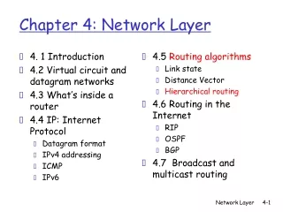
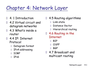
4. 1 Introduction 4.2 Virtual circuit and datagram networks 4.3 What’s inside a router 4.4 IP: Internet Protocol Datagram format IPv4 addressing ICMP IPv6 4.5 Routing algorithms Link state Distance Vector Hierarchical routing 4.6 Routing in the Internet RIP OSPF BGP 4.7 Broadcast and multicast routing Chapter 4: Network Layer Network Layer
transport segment from sending to receiving host on sending side encapsulates segments into datagrams on rcving side, delivers segments to transport layer network layer protocols in every host, router router examines header fields in all IP datagrams passing through it network data link physical network data link physical network data link physical network data link physical network data link physical network data link physical network data link physical network data link physical network data link physical network data link physical network data link physical application transport network data link physical application transport network data link physical Network layer Network Layer
Two Key Network-Layer Functions • forwarding: move packets from router’s input to appropriate router output • routing: determine route taken by packets from source to dest. • routing algorithms analogy: • routing: process of planning trip from source to dest • forwarding: process of getting through single interchange Network Layer
routing algorithm local forwarding table header value output link 0100 0101 0111 1001 3 2 2 1 value in arriving packet’s header 1 0111 2 3 Interplay between routing and forwarding Network Layer
Connection setup • 3rd important function in some network architectures: • ATM, frame relay, X.25 • before datagrams flow, two end hosts and intervening routers establish virtual connection • routers get involved • network vs transport layer connection service: • network: between two hosts • transport: between two processes (end-to-end) Network Layer
4. 1 Introduction 4.2 Virtual circuit (VC) and datagram networks 4.3 What’s inside a router 4.4 IP: Internet Protocol Datagram format IPv4 addressing ICMP IPv6 4.5 Routing algorithms Link state Distance Vector Hierarchical routing 4.6 Routing in the Internet RIP OSPF BGP 4.7 Broadcast and multicast routing Chapter 4: Network Layer Network Layer
Network layer connection and connection-less service • datagram network provides network-layer connectionless service • VC network provides network-layer connection service Network Layer
4 billion IP addresses, so rather than list individual destination address list range of addresses (aggregate table entries) Datagram Forwarding table routing algorithm local forwarding table dest address output link address-range 1 address-range 2 address-range 3 address-range 4 3 2 2 1 IP destination address in arriving packet’s header 1 2 3 Network Layer
Datagram Forwarding table Destination Address Range 11001000 00010111 00010000 00000000 through 11001000 00010111 00010111 11111111 11001000 00010111 00011000 00000000 through 11001000 00010111 00011000 11111111 11001000 00010111 00011001 00000000 through 11001000 00010111 00011111 11111111 otherwise Link Interface 0 1 2 3 Q: but what happens if ranges don’t divide up so nicely? Network Layer
Longest prefix matching Longest prefix matching when looking for forwarding table entry for given destination address, use longest address prefix that matches destination address. Destination Address (DA) Range 11001000 00010111 00010*** ********* 11001000 00010111 00011000 ********* 11001000 00010111 00011*** ********* otherwise Link interface 0 1 2 3 Examples: Which interface? DA: 11001000 00010111 00010110 10100001 Which interface? DA: 11001000 00010111 00011000 10101010 Network Layer
4. 1 Introduction 4.2 Virtual circuit and datagram networks 4.3 What’s inside a router 4.4 IP: Internet Protocol Datagram format IPv4 addressing ICMP IPv6 4.5 Routing algorithms Link state Distance Vector Hierarchical routing 4.6 Routing in the Internet RIP OSPF BGP 4.7 Broadcast and multicast routing Chapter 4: Network Layer Network Layer
Host, router network layer functions: • ICMP protocol • error reporting • router “signaling” • IP protocol • addressing conventions • datagram format • packet handling conventions • Routing protocols • path selection • RIP, OSPF, BGP forwarding table The Internet Network layer Transport layer: TCP, UDP Network layer Link layer physical layer Network Layer
4. 1 Introduction 4.2 Virtual circuit and datagram networks 4.3 What’s inside a router 4.4 IP: Internet Protocol Datagram format IPv4 addressing ICMP IPv6 4.5 Routing algorithms Link state Distance Vector Hierarchical routing 4.6 Routing in the Internet RIP OSPF BGP 4.7 Broadcast and multicast routing Chapter 4: Network Layer Network Layer
IP protocol version number 32 bits total datagram length (bytes) header length (bytes) type of service head. len ver length for fragmentation/ reassembly fragment offset “type” of data flgs 16-bit identifier max number remaining hops (decremented at each router) upper layer time to live header checksum 32 bit source IP address 32 bit destination IP address upper layer protocol to deliver payload to E.g. timestamp, record route taken, specify list of routers to visit. Options (if any) data (variable length, typically a TCP or UDP segment) IP datagram format how much overhead with TCP? • 20 bytes of TCP • 20 bytes of IP • = 40 bytes + app layer overhead Network Layer
network links have MTU (max.transfer size) - largest possible link-level frame. different link types, different MTUs large IP datagram divided (“fragmented”) within net one datagram becomes several datagrams “reassembled” only at final destination IP header bits used to identify, order related fragments IP Fragmentation & Reassembly fragmentation: in: one large datagram out: 3 smaller datagrams reassembly Network Layer
IP Header: Fragmentation • Fields to manage fragmentation • Identification (16 bits) • “Unique ID” for datagram • Original spec said transport layer would set • Flags ( 3 bits) • 1 bit used to say whether there are more fragments following this one in the original datagram • 1 bit used to say “do not fragment” (drop and send error message back to source if need to fragment) • Fragment Offset (13 bits) • Give offset of data in this fragment into original datagram Network Layer
length =1040 length =4000 length =1500 length =1500 ID =x ID =x ID =x ID =x fragflag =1 fragflag =1 fragflag =0 fragflag =0 offset =370 offset =185 offset =0 offset =0 One large datagram becomes several smaller datagrams IP Fragmentation and Reassembly Example • 4000 byte datagram • MTU = 1500 bytes 1480 bytes in data field offset = 1480/8 How would you differentiate a “last fragment” from an unfragmented packet? Network Layer
Start of header Ident = x 0 Offset = 0 Rest of header (a) 1400 data bytes Start of header Ident = x 1 Offset = 0 Rest of header 512 data bytes (b) Start of header Ident = x 1 Offset = 64 Rest of header 512 data bytes Start of header Ident = x 0 Offset = 128 Rest of header 376 data bytes Another Example unfragmented packet ID of the original/unfragmented packet fragmented packets “M (more)” bit in the IP “Flag” field * 8 bytes
Revision - 1 • What is the difference between Routing and Forwarding • Why are ranges of IP addresses stored in forwarding table instead of individual IP addresses. • What is longest prefix matching? • What are the key services provided by network layer? • What is the significance of each field in the IP header. • What is the size of IP header. Network Layer
4. 1 Introduction 4.2 Virtual circuit and datagram networks 4.3 What’s inside a router 4.4 IP: Internet Protocol Datagram format IPv4 addressing ICMP IPv6 4.5 Routing algorithms Link state Distance Vector Hierarchical routing 4.6 Routing in the Internet RIP OSPF BGP 4.7 Broadcast and multicast routing Chapter 4: Network Layer Network Layer
IP address: 32-bit identifier for host, router interface interface: connection between host/router and physical link router’s typically have multiple interfaces host typically has one interface IP addresses associated with each interface 223.1.1.2 223.1.2.2 223.1.2.1 223.1.3.2 223.1.3.1 223.1.3.27 IP Addressing: introduction 223.1.1.1 223.1.2.9 223.1.1.4 223.1.1.3 223.1.1.1 = 11011111 00000001 00000001 00000001 223 1 1 1 Network Layer
IP address: subnet part (high order bits) host part (low order bits) What’s a subnet ? device interfaces with same subnet part of IP address can physically reach each other without intervening router Subnets 223.1.1.1 223.1.2.1 223.1.1.2 223.1.2.9 223.1.1.4 223.1.2.2 223.1.1.3 223.1.3.27 subnet 223.1.3.2 223.1.3.1 network consisting of 3 subnets Network Layer
multicast address 1110 network host 110 network 10 host 32 bits IP Addresses (Classes) “class-full” addressing class 1.0.0.0 to 127.255.255.255 A 0 host network 128.0.0.0 to 191.255.255.255 Unicast B 192.0.0.0 to 223.255.255.255 C 224.0.0.0 to 239.255.255.255 D Multicast 240.0.0.0 to 255.255.255.255 reserved E Reserved 1111 4: Network Layer
Hosts per Class • Class A has ~224 hosts (16777216) • Class B has ~216 hosts (65536) • Class C has ~28 hosts (256) • Class-full addressing: • inefficient use of address space, address space exhaustion • e.g., class B net allocated enough addresses for 65K hosts, even if only 2K hosts in that network 4: Network Layer
IP addressing: CIDR CIDR:Classless InterDomain Routing • subnet portion of address of arbitrary length • address format: a.b.c.d/x, where x is # bits in subnet portion of address host part subnet part 11001000 0001011100010000 00000000 200.23.16.0/23 Network Layer
IP addresses: how to get one? Q: How does a host get IP address? • hard-coded by system admin in a file • Windows: control-panel->network->configuration ->tcp/ip->properties • UNIX: /etc/rc.config • DHCP:Dynamic Host Configuration Protocol: dynamically get address from as server • “plug-and-play” Network Layer
DHCP: Dynamic Host Configuration Protocol Goal: allow host to dynamically obtain its IP address from network server when it joins network Can renew its lease on address in use Allows reuse of addresses (only hold address while connected an “on”) Support for mobile users who want to join network (more shortly) DHCP overview: • host broadcasts “DHCP discover” msg [optional] • DHCP server responds with “DHCP offer” msg [optional] • host requests IP address: “DHCP request” msg • DHCP server sends address: “DHCP ack” msg Network Layer
E B A DHCP client-server scenario 223.1.2.1 DHCP 223.1.1.1 server 223.1.1.2 223.1.2.9 223.1.1.4 223.1.2.2 arriving DHCP client needs address in this network 223.1.1.3 223.1.3.27 223.1.3.2 223.1.3.1 Network Layer
DHCP: more than IP address DHCP can return more than just allocated IP address on subnet: • address of first-hop router for client • name and IP address of DNS sever • network mask (indicating network versus host portion of address) Network Layer
DHCP UDP IP Eth Phy DHCP UDP IP Eth Phy DHCP DHCP DHCP DHCP DHCP DHCP DHCP DHCP DHCP DHCP DHCP: example • connecting laptop needs its IP address, addr of first-hop router, addr of DNS server: use DHCP • DHCP request encapsulated in UDP, encapsulated in IP, encapsulated in 802.1 Ethernet 168.1.1.1 • Ethernet frame broadcast (dest: FFFFFFFFFFFF) on LAN, received at router running DHCP server router (runs DHCP) • Ethernet demuxed to IP demuxed, UDP demuxed to DHCP Network Layer
DHCP UDP IP Eth Phy DHCP UDP IP Eth Phy DHCP DHCP DHCP DHCP DHCP DHCP DHCP DHCP DHCP DHCP: example • DHCP server formulates DHCP ACK containing client’s IP address, IP address of first-hop router for client, name & IP address of DNS server • encapsulation of DHCP server, frame forwarded to client, demuxing up to DHCP at client • client now knows its IP address, name and IP address of DNS server, IP address of its first-hop router router (runs DHCP) Network Layer
IP addresses: how to get one? Q: How does network get subnet part of IP addr? A: gets allocated portion of its provider ISP’s address space ISP's block 11001000 00010111 00010000 00000000 200.23.16.0/20 Organization 0 11001000 00010111 00010000 00000000 200.23.16.0/23 Organization 1 11001000 00010111 00010010 00000000 200.23.18.0/23 Organization 2 11001000 00010111 00010100 00000000 200.23.20.0/23 ... ….. …. …. Organization 7 11001000 00010111 00011110 00000000 200.23.30.0/23 Network Layer
IP addressing: the last word... Q: How does an ISP get block of addresses? A: ICANN: Internet Corporation for Assigned Names and Numbers • allocates addresses • manages DNS • assigns domain names, resolves disputes Network Layer
NAT: Network Address Translation rest of Internet local network (e.g., home network) 10.0.0/24 10.0.0.1 10.0.0.4 10.0.0.2 138.76.29.7 10.0.0.3 Datagrams with source or destination in this network have 10.0.0/24 address for source, destination (as usual) All datagrams leaving local network have same single source NAT IP address: 138.76.29.7, different source port numbers Network Layer
NAT: Network Address Translation • Motivation: local network uses just one IP address as far as outside world is concerned: • range of addresses not needed from ISP: just one IP address for all devices • can change addresses of devices in local network without notifying outside world • can change ISP without changing addresses of devices in local network • devices inside local net not explicitly addressable, visible by outside world (a security plus). Network Layer
NAT: Network Address Translation Implementation: NAT router must: • outgoing datagrams:replace (source IP address, port #) of every outgoing datagram to (NAT IP address, new port #) . . . remote clients/servers will respond using (NAT IP address, new port #) as destination addr. • remember (in NAT translation table) every (source IP address, port #) to (NAT IP address, new port #) translation pair • incoming datagrams:replace (NAT IP address, new port #) in dest fields of every incoming datagram with corresponding (source IP address, port #) stored in NAT table Network Layer
2 4 1 3 S: 138.76.29.7, 5001 D: 128.119.40.186, 80 S: 10.0.0.1, 3345 D: 128.119.40.186, 80 1: host 10.0.0.1 sends datagram to 128.119.40.186, 80 2: NAT router changes datagram source addr from 10.0.0.1, 3345 to 138.76.29.7, 5001, updates table S: 128.119.40.186, 80 D: 10.0.0.1, 3345 S: 128.119.40.186, 80 D: 138.76.29.7, 5001 NAT: Network Address Translation NAT translation table WAN side addr LAN side addr 138.76.29.7, 5001 10.0.0.1, 3345 …… …… 10.0.0.1 10.0.0.4 10.0.0.2 138.76.29.7 10.0.0.3 4: NAT router changes datagram dest addr from 138.76.29.7, 5001 to 10.0.0.1, 3345 3: Reply arrives dest. address: 138.76.29.7, 5001 Network Layer
NAT: Network Address Translation • 16-bit port-number field: • 60,000 simultaneous connections with a single LAN-side address! • NAT is controversial: • routers should only process up to layer 3 • violates end-to-end argument • NAT possibility must be taken into account by app designers, e.g., P2P applications • address shortage should instead be solved by IPv6 Network Layer
4. 1 Introduction 4.2 Virtual circuit and datagram networks 4.3 What’s inside a router 4.4 IP: Internet Protocol Datagram format IPv4 addressing ICMP IPv6 4.5 Routing algorithms Link state Distance Vector Hierarchical routing 4.6 Routing in the Internet RIP OSPF BGP 4.7 Broadcast and multicast routing Chapter 4: Network Layer Network Layer
used by hosts & routers to communicate network-level information error reporting: unreachable host, network, port, protocol echo request/reply (used by ping) network-layer “above” IP: ICMP msgs carried in IP datagrams ICMP message: type, code plus first 8 bytes of IP datagram causing error ICMP: Internet Control Message Protocol TypeCodedescription 0 0 echo reply (ping) 3 0 dest. network unreachable 3 1 dest host unreachable 3 2 dest protocol unreachable 3 3 dest port unreachable 3 6 dest network unknown 3 7 dest host unknown 4 0 source quench (congestion control - not used) 8 0 echo request (ping) 9 0 route advertisement 10 0 router discovery 11 0 TTL expired 12 0 bad IP header Network Layer
4. 1 Introduction 4.2 Virtual circuit and datagram networks 4.3 What’s inside a router 4.4 IP: Internet Protocol Datagram format IPv4 addressing ICMP IPv6 4.5 Routing algorithms Link state Distance Vector Hierarchical routing 4.6 Routing in the Internet RIP OSPF BGP 4.7 Broadcast and multicast routing Chapter 4: Network Layer Network Layer
IPv6 • Initial motivation:32-bit address space soon to be completely allocated. • Additional motivation: • header format helps speed processing/forwarding • header changes to facilitate QoS IPv6 datagram format: • fixed-length 40 byte header • no fragmentation allowed Network Layer
IPv6 Header (Cont) Priority: identify priority among datagrams in flow Flow Label: identify datagrams in same “flow.” (concept of“flow” not well defined). Next header: identify upper layer protocol for data pri ver flow label hop limit payload len next hdr source address (128 bits) destination address (128 bits) data 32 bits Network Layer
Other Changes from IPv4 • Checksum:removed entirely to reduce processing time at each hop • Options: allowed, but outside of header, indicated by “Next Header” field • ICMPv6: new version of ICMP • additional message types, e.g. “Packet Too Big” • multicast group management functions Network Layer
Transition From IPv4 To IPv6 • Not all routers can be upgraded simultaneous • no “flag days” • How will the network operate with mixed IPv4 and IPv6 routers? • Tunneling: IPv6 carried as payload in IPv4 datagram among IPv4 routers Network Layer
F A B E F E B A tunnel Logical view: IPv6 IPv6 IPv6 IPv6 Physical view: IPv6 IPv6 IPv6 IPv6 IPv4 IPv4 Tunneling Network Layer
Flow: X Src: A Dest: F data Flow: X Src: A Dest: F data Flow: X Src: A Dest: F data Flow: X Src: A Dest: F data A B E F F A B E C D Src:B Dest: E Src:B Dest: E Tunneling tunnel Logical view: IPv6 IPv6 IPv6 IPv6 Physical view: IPv6 IPv6 IPv6 IPv6 IPv4 IPv4 A-to-B: IPv6 E-to-F: IPv6 B-to-C: IPv6 inside IPv4 B-to-C: IPv6 inside IPv4 Network Layer
4. 1 Introduction 4.2 Virtual circuit and datagram networks 4.3 What’s inside a router 4.4 IP: Internet Protocol Datagram format IPv4 addressing ICMP IPv6 4.5Routing algorithms Link state Distance Vector Hierarchical routing 4.6 Routing in the Internet RIP OSPF BGP 4.7 Broadcast and multicast routing Chapter 4: Network Layer Network Layer