
5 + 5
A possible T1 trigger architecture ( 1a). 1 fiber = 16 Trigger bits Multiplicity encoded in 4 (5) bits. 10. 10. 5 + 5. OptoRx 1. 4 bit * 10 out of 64. +. To LONEG Inputs. 40 out of 64 lines. Merger. OptoRx 2. > L1 . SL. +. 32 + 12 diff. lines.

5 + 5
E N D
Presentation Transcript
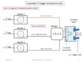
A possible T1 trigger architecture (1a). 1 fiber = 16 Trigger bits Multiplicity encoded in 4 (5) bits 10 10 5+5 OptoRx 1 4bit * 10 out of 64 + To LONEG Inputs 40 out of 64 lines Merger OptoRx 2 > L1 SL + 32 + 12 diff. lines (4bit*5+ 4bit*5) out of 64 SL OptoRx 3 + S-Link 64 Connectors 2bit * 10 out of 64 L1 + trigger code Saverio MINUTOLI - Technical Board
A possible T1 trigger architecture (1b). 1 fiber = 16 Trigger bits Multiplicity encoded in 5 bits Majority 3 Thresholds encoded in 2 bits 0 < Thr_1 < Thr_2 < Thr_3 < 16. 10 10 5+5 OptoRx 1 2bit * 10 out of 64 < + To LONEG Inputs 20 out of 64 lines Merger OptoRx 2 L1 SL + > 32 + 12 diff. lines (2bit*5+ 2bit*5) out of 64 SL OptoRx 3 + > S-Link 64 Connectors 2bit * 10 out of 64 L1 + trigger code Saverio MINUTOLI - Technical Board
A possible T1 trigger architecture (2). 12 fibers = 3 * 4 Layers (1 to 4) @ full resolution, 8 Trigger bits/VFAT 16 bits/CSC 3 fibers = 3 * 1 Layer (5) @ half full resolution, 4 Trigger bits/VFAT 8 Tbits/CSC 24 Tbits + 3 DAV signals = 27 lines 12 12 3+3 OptoRx 1 16.. Tracks +x<> To LONEG Inputs 27 OptoRx 2 Merger FPGA SL 64 = 27 + 27 + 10 free 32 + 12 diff. lines SL OptoRx 3 27 <>x+ S-Link 64 Connectors 16.. Tracks 12 fibers = 3 * 4 Layers (1 to 4) @ full resolution, 8 Trigger bits/VFAT 16 bits/CSC 3 fibers = 3 * 1 Layer (5) @ half full resolution, 4 Trigger bits/VFAT 8 Tbits/CSC 24 Tbits + 3 DAV signals = 27 lines Saverio MINUTOLI - Technical Board
T1 trigger (1a) implementation. OptoRx FPGA Fiber Receiver Glitch Filter TbitMask Chamber Multiplicity 16 Tbit 16 16 4 Comp S P #1 CLA Fibers In 12 16 Tbit 16 16 4 Comp CLA S P #12 En/Dis En/Dis Saverio MINUTOLI - Technical Board
T1 trigger (1a) implementation. Merger FPGA Option 1 Layer Majority Layer Multiplicity Decider 4 * 10 OR1 Comp CLA + > L1 4 * 10 To LONEG OR2 Comp CLA Trigger code 4 * 10 OR3 Comp CLA Saverio MINUTOLI - Technical Board
T1 trigger (1a) implementation. Merger FPGA Option 2 Chamber Majority Layer Multiplicity Decider 4 * 10 OR1 Comp CLA + > L1 4 * 10 To LONEG OR2 Comp CLA Trigger code 4 * 10 OR3 Comp CLA Bypassed Sextant Roads Saverio MINUTOLI - Technical Board
T1 trigger (1b) implementation. OptoRx FPGA Chamber Majority Fiber Receiver Glitch Filter TbitMask Chamber Multiplicity 2 16 Tbit 16 16 4 Comp S P #1 CLA Fibers In 12 2 16 Tbit 16 16 4 Comp CLA S P #12 En/Dis En/Dis Saverio MINUTOLI - Technical Board
T1 trigger (1b) implementation. Merger FPGA Decider 2 * 10 OR1 L1 2 * 10 To LONEG OR2 Trigger code 2 * 10 OR3 Saverio MINUTOLI - Technical Board