Download

1 / 28
280 likes | 468 Vues
SIMULATION OF GAS PIPELINES LEAKAGE USING CHARACTERISTICS METHOD. Author: Ehsan Nourollahi Organization: NIGC (National Iranian Gas Company) Department of Mechanical Engineering , Ferdowsi University, Iran. Topics:. Introduction Characteristics method

E N D
SIMULATION OF GAS PIPELINES LEAKAGE USING CHARACTERISTICS METHOD Author: Ehsan Nourollahi • Organization: NIGC (National Iranian Gas Company) • Department of Mechanical Engineering , Ferdowsi University, Iran
Topics: Introduction Characteristics method The numerical solution method & The implementation of the leakage effect Results & Conclusions
The pipe surface leakage or the pipe section dismissal can be created of some various reasons like as corrosion, earthquake or mechanical stroke which may be implemented in the pipe surface and also overload compressors. Figure (1) After the leakage creation, the flat expansion pressure waves are propagated in two converse sidesThese waves have the sonic speed and after clashing to the upstream and downstream boundaries, return to the form of compression or expansion wave depending on the edge type
In the leak location, depending on ratio of pressure to ambient pressure be more or less than CPR quantity, the flow will be sonic and ultrasonic or subsonic respectively.If the flow be sonic and ultra sonic, the sonic reporter wave don’t leak from out of the pipe to inter the pipe practically. Hence the changes of the flow field are accomplished due to the flat pressure waves and the real boundary conditions on the start and end of the pipemass flow outlet of the hole only depends on the stagnation pressure in the leak location and on area of the hole and is not related to the form of the orifice cross section
The continuity equation is: The momentum equation is:By extension of these equation, we have:With attention to the definition of speed of the sound by:For an ideal gas:
Third condition of continuity for isentropic flow is:or:For isentropic flow are constant, then we have:
By using of the relationship between the sonic speed and the pressure in an ideal gas, these equations are changed to the below forms after some steps of rewriting of the mass and momentum conservation equations:These equations are set of quasi-linear hyperbolic partial differential equations.
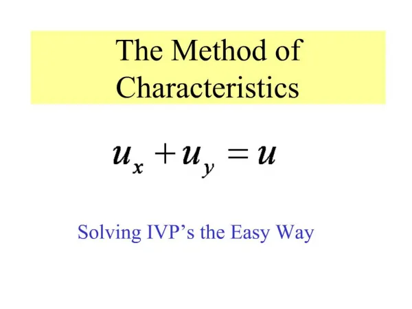
Therefore a solution of the form: is required. Except of special cases, there are no analytical solution for these equations, then we should study numerical solutions. In this paper we use Characteristics method to achieve a numerical solution. Base of this method is transferring of two independent equations as and to another group as or
The solution may be represented by the curved surface bounded by edges PQRS Figure 2. Graphical interpretation of the characteristics method (a) Three-dimensional surface defining (b) Projection of line on characteristics surface to plane at
if in a special point on the surface of for a reviewing special curve from that point, the slope of the projected curve on the x-t plane be equal with quantity of curve of that point, the passing direction of that point is known as the characteristic direction. We have in mathematical expression:By using of this complete derivative definition, the sonic speed and particle speed parameters are determined with respect to the time of a characteristic length like as the below:
Therefore if defined as the form of: In length of two characteristics, they are rewritten like as:
The numerical solution method At first the none-dimensional parameters of A and U are defined as below in the characteristics method: In the above equation is sonic speed in the start point. Then Reimann non-dimensional characteristics are defined as following:
An explicit equation between Reimann variables in inner points of the solution field is presented below which is for each step:By distinction of the state equation in the boundary, a mono-equation is created between Reimann variables. So always in any boundary, one of these variables is known and the other one is unknown then the unknown Reimann variable can be calculated, so the effect of the boundary transfers to the solution field is obtained.
The implementation of the leakage effect For implementation of the leakage effect on the flow field, the mesh is chosen in a way that the hole location would be stated between two nodes When the hole is created in the pipe surface, as it’s said, the pressure ratio to the ambient pressure in below the hole which is inter the pipe, is more than the CPR in the later time steps. Figure (3)
Therefore, the flow is checked in the hole location and outflow of the leak location, calculated by: The leakage point in any time step act as a boundary and two expansion waves depending to direction of flow in the pipe, would reach to a andb points with a little time difference and create the same change in non-dimensional speed of Ulike the below form:
Then the unknown parameters and are calculated like the below form:Therefore, the state of two points in any time step with considering to corrected leakage effect and hence by notice to the equations that governed to the problem are type of the hyperbolic equations, during the time of the leakage effect is transferred permanently as a third boundary addition to the upstream and downstream boundaries to the solution field.
Consumptions:Pipe Length : 250 meter Hole Area : 1 cmNumber of grid system : 100 nodesInitial gas pressure : 30 bar Initial gas speed : 41 ft/sAlso temperature is constant and there are non viscose flow. Boundary conditions: Upstream boundary condition is the reservoir with constant pressure and the downstream boundary condition is stated with three forms: • The boundary with no changes with respect to the location • The valve with constant coefficient of pressure drop • close end
Figure 4. State (1) of the boundary conditions: 4-a Pressure changes by increasing of the pipe length at primary times 4-b Changes of the exit mass flux by time
Figure 5. State (1) of the boundary conditions:5-a changes of the exit mass flux by increasing the hole area and pipe length5-b changes of the exit mass flux by increasing the pipe pressure and pipe length
Figure 6. State (2) of the boundary conditions:6-a. Pressure changes by increasing of the pipe length at primary times6-b. Changes of the exit mass flux by time
Figure 7. State (2) of the boundary conditions:7-a Changes of the exit mass flux by increasing the hole area and pipe length7-b Changes of the exit mass flux by increasing the pipe pressure and pipe length
Figure 8. state (3) of the boundary conditions:8-a Pressure changes by increasing of the pipe length at primary times8-b Changes of the exit mass flux by time
Figure 9. State (2) of the boundary conditions:9-a Changes of the exit mass flux by increasing the hole area and pipe length9-b Changes of the exit mass flux by increasing the pipe pressure and pipe length