
Big Idea: Stored-Program Concept
CS61C : Machine Structures Lecture 3.1.2 MIPS Instruction Format 2004-07-06 Kurt Meinz inst.eecs.berkeley.edu/~cs61c. Big Idea: Stored-Program Concept. Computers built on 2 key principles: 1) Instructions are represented as data.

Big Idea: Stored-Program Concept
E N D
Presentation Transcript
CS61C : Machine StructuresLecture 3.1.2MIPS Instruction Format2004-07-06Kurt Meinzinst.eecs.berkeley.edu/~cs61c
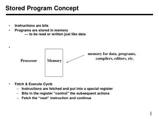
Big Idea: Stored-Program Concept Computers built on 2 key principles: 1) Instructions are represented as data. 2) Therefore, entire programs can be stored in memory to be read or written just like data.
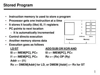
Consequence: Everything Addressed • Everything has a memory address: instructions, data words • One register keeps address of instruction being executed: “Program Counter” (PC) • Basically a pointer to memory: Intel calls it Instruction Address Pointer, a better name • Computer “brain” executes the instruction at PC • Jumps and branches modify PC
Instructions as Numbers (1/2) • Currently all data we work with is in words (32-bit blocks): • Each register is a word. • lw and sw both access memory one word at a time. • So how do we represent instructions? • Remember: Computer only understands 1s and 0s, so “add $t0,$0,$0” is meaningless. • MIPS wants simplicity: since data is in words, make instructions be words too
Instructions as Numbers (2/2) • One word is 32 bits, so divide instruction word into “fields”. • Each field tells computer something about instruction. • 3 basic types of instruction formats: • R-format • I-format • J-format
Instruction Formats • I-format: used for instructions with immediates, lw and sw (since the offset counts as an immediate), and the branches (beq and bne), • (but not the shift instructions; later) • J-format: used for j and jal • R-format: used for all other instructions
6 5 5 5 5 6 opcode rs rt rd shamt funct R-Format Instructions (1/5) • Define “fields” of the following number of bits each: 6 + 5 + 5 + 5 + 5 + 6 = 32 • For simplicity, each field has a name: • Important: On these slides and in book, each field is viewed as a 5- or 6-bit unsigned integer, not as part of a 32-bit integer. 5-bit fields 0-31, 6-bit fields 0-63.
R-Format Instructions (2/5) • What do these field integer values tell us? • opcode: partially specifies what instruction it is • Note: This number is equal to 0 for all R-Format instructions. • funct: combined with opcode, this number exactly specifies the instruction
R-Format Instructions (3/5) • More fields: • rs (Source Register): generally used to specify register containing first operand • rt (Target Register): generally used to specify register containing second operand (note that name is misleading) • rd (Destination Register): generally used to specify register which will receive result of computation
R-Format Instructions (4/5) • Notes about register fields: • Each register field is exactly 5 bits, which means that it can specify any unsigned integer in the range 0-31. Each of these fields specifies one of the 32 registers by number. • The word “generally” was used because there are exceptions that we’ll see later. E.g., • mult and div have nothing important in the rd field since the dest registers are hi and lo • mfhi and mflo have nothing important in the rs and rt fields since the source is determined by the instruction (p. 264 P&H)
R-Format Instructions (5/5) • Final field: • shamt: This field contains the amount a shift instruction will shift by. Shifting a 32-bit word by more than 31 is useless, so this field is only 5 bits (so it can represent the numbers 0-31). • This field is set to 0 in all but the shift instructions. • For a detailed description of field usage for each instruction, see back inside cover of P&H textbook • (We’ll give you a copy for any exam)
R-Format Example (1/2) • MIPS Instruction: add $8,$9,$10 opcode = 0 (look up in table in book) funct = 32 (look up in table in book) rs = 9 (first operand) rt = 10 (second operand) rd = 8 (destination) shamt = 0 (not a shift)
000000 0 01001 9 01010 10 01000 8 00000 0 100000 32 hex R-Format Example (2/2) • MIPS Instruction: add $8,$9,$10 Decimal number per field representation: Binary number per field representation: hex representation: 012A 4020hex decimal representation: 19,546,144ten • Called a Machine Language Instruction
I-Format Instructions (1/4) • What about instructions with immediates (e.g. addi and lw)? • 5-bit field only represents numbers up to the value 31: immediates may be much larger than this • Ideally, MIPS would have only one instruction format (for simplicity): unfortunately, we need to compromise • Define new instruction format that is partially consistent with R-format: • Notice that, if instruction has an immediate, then it uses at most 2 registers.
opcode 6 rs 5 rt 5 immediate 16 I-Format Instructions (2/4) • Define “fields” of the following number of bits each: 6 + 5 + 5 + 16 = 32 bits • Again, each field has a name: • Key Concept: Only one field is inconsistent with R-format. Most importantly, opcode is still in same location.
I-Format Instructions (3/4) • What do these fields mean? • opcode: same as before except that, since there’s no funct field, opcode uniquely specifies an instruction in I-format • This also answers question of why R-format has two 6-bit fields to identify instruction instead of a single 12-bit field: in order to be consistent with other formats. • rs: specifies the only register operand (if there is one) • rt: specifies register which will receive result of computation (this is why it’s called the target register “rt”)
I-Format Instructions (4/4) • The Immediate Field: • addi, slti, sltiu, the immediate is sign-extended to 32 bits. Thus, it’s treated as a signed integer. • 16 bits can be used to represent immediate up to 216 different values • This is large enough to handle the offset in a typical lw or sw, plus a vast majority of values that will be used in the slti instruction.
I-Format Example (1/2) • MIPS Instruction: addi $21,$22,-50 opcode = 8 (look up in table in book) rs = 22 (register containing operand) rt = 21 (target register) immediate = -50 (by default, this is decimal)
001000 8 10110 22 10101 21 1111111111001110 -50 I-Format Example (2/2) • MIPS Instruction: addi $21,$22,-50 Decimal/field representation: Binary/field representation: hexadecimal representation: 22D5 FFCEhex decimal representation: 584,449,998ten
I-Format Problems (0/3) • Problem 0: Unsigned # sign-extended? • addiu, sltiu, sign-extends immediates to 32 bits. Thus, # is a “signed” integer. • Rationale • addiu so that can add w/out overflow • See K&R pp. 230, 305 • sltiu suffers so that we can have ez HW • Does this mean we’ll get wrong answers? • Nope, it means assembler has to handle any unsigned immediate 215 ≤ n < 216 (I.e., with a 1 in the 15th bit and 0s in the upper 2 bytes) as it does for numbers that are too large.
I-Format Problems (1/3) • Problem 1: • Chances are that addi, lw, sw and slti will use immediates small enough to fit in the immediate field. • …but what if it’s too big? • We need a way to deal with a 32-bit immediate in any I-format instruction.
I-Format Problems (2/3) • Solution to Problem 1: • Handle it in software + new instruction • Don’t change the current instructions: instead, add a new instruction to help out • New instruction: lui register, immediate • stands for Load Upper Immediate • takes 16-bit immediate and puts these bits in the upper half (high order half) of the specified register • sets lower half to 0s
I-Format Problems (3/3) • Solution to Problem 1 (continued): • So how does lui help us? • Example: addi $t0,$t0, 0xABABCDCD becomes: lui $at, 0xABAB ori $at, $at, 0xCDCD add $t0,$t0,$at • Now each I-format instruction has only a 16-bit immediate. • Wouldn’t it be nice if the assembler would this for us automatically? (later)
J-Format Instructions (1/5) Jumps modify the PC: “j <label>” means “Set the next PC = the address of the instruction pointed to by <label>”
J-Format Instructions (1/5) Jumps modify the PC: • j and jal jump to labels • but a label is just a name for an address! • so, the ML equivalents of j and jal use addresses • Ideally, we could specify a 32-bit memory address to jump to. • Unfortunately, we can’t fit both a 6-bit opcode and a 32-bit address into a single 32-bit word, so we compromise:
6 bits opcode target address 26 bits J-Format Instructions (2/5) • Define fields of the following number of bits each: • As usual, each field has a name: • Key Concepts • Keep opcode field identical to R-format and I-format for consistency. • Combine all other fields to make room for large target address.
J-Format Instructions (3/5) • target has 26 bits of the 32-bit bit address. • Optimization: • jumps will only jump to word aligned addresses, • so last two bits of address are always 00 (in binary). • let’s just take this for granted and not even specify them.
J-Format Instructions (4/5) • Now : we have 28 bits of a 32-bit address • Where do we get the other 4 bits? • By definition, take the 4 highest-order bits from the PC. • Technically, this means that we cannot jump to anywhere in memory, but it’s adequate 99.9999…% of the time, since programs aren’t that long • only if jump straddles a 256 MB boundary • If we absolutely need to specify a 32-bit address, we can always put it in a register and use the jr instruction.
J-Format Instructions (5/5) • Summary: • Next PC = { PC[31..28], target address, 00 } • Understand where each part came from! • Note: { , , } means concatenation { 4 bits , 26 bits , 2 bits } = 32 bit address • { 1010, 11111111111111111111111111, 00 } = 10101111111111111111111111111100 • Note: Book uses ||, Verilog uses { , , } • We will learn Verilog later in this class
Midterm details • Email Carolen NOW if you can’t make it • You will write C and MIPS. • “I Highly Recommend review session.”
opcode 0 $reg rs rt 0 rd 0 shamt 0 funct 8 Other Jumps and Branches • We have j and jal • What about jr? • J-format won’t work (no reg field) • So, use R-format and ignore other regs: • What about beq and bne? • Tight fit: 2 regs and an immediate (address)
opcode rs rt immediate Branches: PC-Relative Addressing (1/5) • Use I-Format • opcode specifies beq v. bne • rs and rt specify registers to compare • What can immediate specify? • Immediate is only 16 bits • Using word-align trick, we can get 18 bits • Still not enough! • Would have to use jr if straddling a 256KB.
Branches: PC-Relative Addressing (2/5) • How do we usually use branches? • Answer: if-else, while, for • Loops are generally small: typically up to 50 instructions • Function calls and unconditional jumps are done using jump instructions (j and jal), not the branches. • Conclusion: may want to branch to anywhere in memory, but a branch often changes PC by a small amount…
Branches: PC-Relative Addressing (3/5) • Solution to branches in a 32-bit instruction: PC-Relative Addressing • Let the 16-bit immediate field be a signed two’s complement integer to be added to the PC if we take the branch. • Now we can branch ± 215 words from the PC, which should be enough to cover almost any loop.
Branches: PC-Relative Addressing (5/5) • Branch Calculation: • If we don’t take the branch: next PC = PC + 4 PC+4 = byte address of next instruction • If we do take the branch: next PC = (PC + 4) + (immediate * 4) • Observations • Immediate field specifies the number of words to jump, which is simply the number of instructions to jump. • Immediate field can be positive or negative. • Due to hardware, add immediate to (PC+4), not to PC; will be clearer why later in course
Branch Example (1/3) • MIPS Code: Loop: beq $9,$0,End add $8,$8,$10 addi $9,$9,-1 j Loop End: sub $2,$3,$4 • beq branch is I-Format: opcode = 4 (look up in table) rs = 9 (first operand) rt = 0 (second operand) immediate = ???
Branch Example (2/3) • MIPS Code: Loop: beq $9,$0,End addi $8,$8,$10 addi $9,$9,-1 j Loop End: sub $2,$3,$4 • Immediate Field: • Number of instructions to add to (or subtract from) the PC, starting at the instruction following the branch (“+4”). • In beq case, immediate = 3
000100 4 01001 9 00000 0 0000000000000011 3 Branch Example (3/3) • MIPS Code: Loop: beq $9,$0,End addi $8,$8,$10 addi $9,$9,-1 j Loop End: sub $2,$3,$4 decimal representation: binary representation:
Questions on PC-addressing • Does the value in branch field change if we move the code? • What do we do if destination is > 215 instructions away from branch?
J target address opcode R opcode opcode rs rs rt rt rd immediate shamt funct I MIPS So Far: • MIPS Machine Language Instruction: 32 bits representing a single instruction • Branches use PC-relative addressing, Jumps use PC-absolute addressing.
Review from before: lui • So how does lui help us? • Example: addi $t0,$t0, 0xABABCDCD becomes: lui $at, 0xABAB ori $at, $at, 0xCDCD add $t0,$t0,$at • Now each I-format instruction has only a 16-bit immediate. • Wouldn’t it be nice if the assembler would this for us automatically? • If number too big, then just automatically replace addi with lui, ori, add
True Assembly Language (1/3) • Pseudoinstruction: A MIPS instruction that doesn’t turn directly into a machine language instruction, but into other MIPS instrucitons • What happens with pseudoinstructions? • They’re broken up by the assembler into several “real” MIPS instructions. • But what is a “real” MIPS instruction? Answer in a few slides • First some examples…
Example Pseudoinstructions • Register Move movereg2,reg1 Expands to: add reg2,$zero,reg1 • Load Immediate lireg,value If value fits in 16 bits: addi reg,$zero,value else: lui reg,upper 16 bits of value ori reg,$zero,lower 16 bits
True Assembly Language (2/3) • Problem: • When breaking up a pseudoinstruction, the assembler may need to use an extra reg. • If it uses any regular register, it’ll overwrite whatever the program has put into it. • Solution: • Reserve a register ($1, called $at for “assembler temporary”) that assembler will use to break up pseudo-instructions. • Since the assembler may use this at any time, it’s not safe to code with it.
0 0 Example Pseudoinstructions • Rotate Right Instruction ror reg, value Expands to: srl $at, reg, value sll reg, reg, 32-value or reg, reg, $at • No operation instruction nop Expands to instruction = 0ten, sll $0, $0, 0
True Assembly Language (3/3) • MAL (MIPS Assembly Language): the set of instructions that a programmer may use to code in MIPS; this includes pseudoinstructions • TAL (True Assembly Language): set of instructions that can actually get translated into a single machine language instruction (32-bit binary string) • A program must be converted from MAL into TAL before translation into 1s & 0s.
Questions on Pseudoinstructions • Question: • How does MIPS recognize pseudo-instructions? • Answer: • It looks for officially defined pseudo-instructions, such as ror and move • It looks for special cases where the operand is incorrect for the operation and tries to handle it gracefully
Decoding Machine Language • How do we convert 1s and 0s to C code? Machine language C? • For each 32 bits: • Look at opcode: 0 means R-Format, 2 or 3 mean J-Format, otherwise I-Format. • Use instruction type to determine which fields exist. • Write out MIPS assembly code, converting each field to name, register number/name, or decimal/hex number. • Logically convert this MIPS code into valid C code. Always possible? Unique?
Decoding Example (1/7) • Here are six machine language instructions in hexadecimal: 00001025hex 0005402Ahex 11000003hex 00441020hex 20A5FFFFhex 08100001hex • Let the first instruction be at address 4,194,304ten (0x00400000hex). • Next step: convert hex to binary
J target address 2 or 3 R 1, 4-31 0 rs rs rt rt rd immediate shamt funct I Decoding Example (2/7) • The six machine language instructions in binary: 0000000000000000000100000010010100000000000001010100000000101010000100010000000000000000000000110000000001000100000100000010000000100000101001011111111111111111 00001000000100000000000000000001 • Next step: identify opcode and format


![[Big Idea]](https://cdn3.slideserve.com/6855908/big-idea-dt.jpg)