Download
1 / 29
2.09k likes | 5.58k Vues
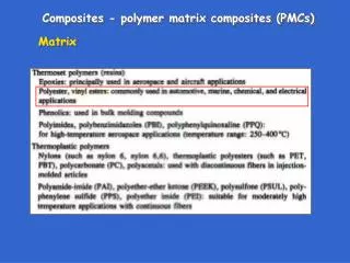
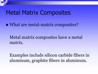
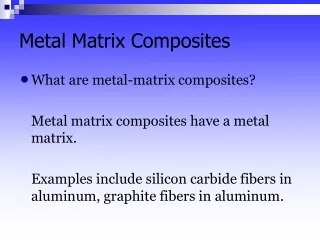
Metal Matrix Composites (MMC). Purpose of using MMCs. higher specific modulus and strength better properties at elevated temperature lower CTE better wear resistance Disadvantages of using MMCs: less toughness more expensive. Applications of MMCs.

E N D
Purpose of using MMCs • higher specific modulus and strength • better properties at elevated temperature • lower CTE • better wear resistance Disadvantages of using MMCs: • less toughness • more expensive
Applications of MMCs Mid-fuselage structure of Space Shuttle Orbiter showing boron-aluminum tubes. (Photo courtesy of U.S. Air Force/NASA). Cast SiCp/Al attachment fittings: (a-top) multi-inlet fitting for a truss node
MMC processing • solid-state processing: suitable for composite with large surface area of high energy solid-gas interface, e.g. matrix in particle or fail form. • diffusion bonding: using foil matrix Fig 3.1 e.g. Ti, Ni, Cu, Al reinforced with boron • power metallurgy: using particle materials, suitable for particle or whisker reinforced composites, Vf < 25% • co-extrusion, drawing limited to ductile reinforcement and matrix
liquid-state processing • Casting Difficulties: wetting chemical reaction non-uniform mixing (due to density difference) , can be improved by • using precoating on reinforcements, e.g. pyrolitic graphite coating • modifying the melt, e.g. add Li in Al melt • compo casting, rheocasting: • infiltration on perform: • squeeze casting: Fig 3.2
Deposition processing • spray co-deposition, Fig 3.4 • chemical and physical vapour deposition (e.g. tungsten) • electroplating (e.g. nickel) • sputtering and plasma spraying
In-situ processing Unidirectional laminar or rod-like eutectic alloys, Fig 3.5 (in-situ composites)
Interface reactions Interdiffusion between matrix and reinforcement: Where x = extent of interdiffusion Dd = diffusion coefficient Interdiffusion interfacial layer (Fig 3.6) mechanical properties are degraded (Fig 3.7)
Mechanical properties of MMCs lower CTE than metals (Fig 3.8) lower coefficient of thermal and electrical conductivity (Table 3.2) higher thermal deformation resistance improvement in stiffness (Fig 3.9, Fig 3.10) strength and ductility Reinforcement-matrix interface: Strong high strength Extensive interaction low strength, low fatigue resistance Fig 3.12~Fig 3.17 creep (Fig 3.18, Fig 3.19) fatigue (Table 3.4, Fig 3.20)
Commercial MMCs • Multi-filamentary superconductor