Download

1 / 17
190 likes | 435 Vues
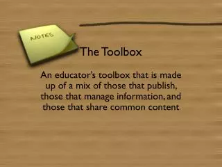
What Tools Do You Use To Erect The Building?. Here Is Your Tool Box. Bringing the 3D Model to your Toolbox. Click on your Toolbox to See What else is Inside. Exit. Don’t Forget to Visit us at www.tekla.com.

E N D
What Tools Do You Use To Erect The Building? Here Is Your Tool Box Bringing the 3D Model to your Toolbox Click on your Toolbox to See What else is Inside Exit
Don’t Forget to Visit us at www.tekla.com Tekla Structures is a 3D Solution used by Structural Engineers, Steel Detailers,Steel Fabricators, and General Contractors world wide. Exit It Can be used by you too! Where Does the Model Come From? Avoid Erection Problems Stay On Schedule Click The Links Above for More Information
Don’t Forget to Visit us at www.tekla.com Tekla Structures is a 3D Solution used by Structural Engineers, Steel Detailers,Steel Fabricators, and General Contractors world wide. Exit Where Does the Model Come From? Avoid Erection Problems Stay On Schedule Click The Links Above for More Information
Where Does the Model Come From? Go Back Who Creates the 3D Model? You Can Even Send Comments & Project Status back First Let’s Introduce the Players How Does that Model Get to You? You Don’t Build The 3D Model, you utilize it’s Information Structural Engineer General Contractor Steel Erector Steel Detailer Steel Fabricator Are my Projects Modeled in Tekla Structures? You might get the model from the Steel Detailer directly, the Fabricator, or even the General Contractor depending on how the contract is organized. Visually show erection progress, erectability issues, and field discrepancies, back to the fabricator, detailer, and contractor. Click Here to See Projects Detailed, Fabricated, and Erected with Tekla Structures
Global Projects Go Back Click here These are some of the prestigious projects done in Tekla Structures. However a large portion of our user base is smaller to mid size companies, and Tekla Structures is used on projects ranging from grocery stores and canopies to stadiums and skyscrapers. • Hillside Community Church, CA • Steel Tech Industrial Corp.
Go Back User Showcase “My detailing department supplies me with a Tekla model before starting each job so that I can review the conditions and prepare erection sequences even before I hit the jobsite” - Steve Rodriguez, Erection Superintendent “Ever since I started using the Tekla viewing station on my laptop in the field, I am able to check dimensional design information versus the actual field conditions clarifying many complicated areas and solving most unanswered questions” Featuring: - Hillside Community Church, Alta Loma, California
Avoid Erection Problems Go Back Review Connections and Assemblies in 3D Review Safety Cable and Tie Off Requirements Discover Clearance & Installation Issues Visually Communicate Erectability Issues Click The Links Above for More Information
Review Connections & Assemblies in 3D Go Back The Erector Can Query the Assembly to see which parts are shop bolted and welded together vs. being field installed. In this case the Erector can verify the detailer shop attached the bent plate pourstop (bright yellow) to the top of the beam. He can also see the gusset plates were shop attached to the beam and then they will be field bolted to the column.
Review Safety Requirements • The Erector can clearly see the detailer applied the appropriate Safety Cable holes in the column. Go Back • He can also see that a closure plate will be required where the bent plate pourstop wraps around the column. • Safety Tie off holes on the beam flanges can be verified as well
Visually Communicate Erectability Issues Go Back The 3D Model makes it easier to illustrate installation issues The Erector can Markup and Colorize the model to show problem areas that may need to be fixed in detailing before fabrication, as well as identifying field discrepancies during erection.
Visually Schedule, Plan, and Track the Project Go Back Plan Erection Sequences and Site Equipment Locations Visually Plan Truck Loads Track and Animate Deliveries and Erection Progress Report Assembly Weights and Center of Gravity Click The Links Above for More Information
Plan Erection Sequences and Site Equipment Locations Go Back Reference in Cranes, Trucks, Generators, etc. Define, Show, and Anitmate Sequences by Color & Transparency
Report Assembly Weights and Center of Gravity Go Back Query the Center of Gravity on Asymmetrical Assemblies for Crane Choke Point and Lifting Lug Placement. Also Generate Push of the button reports with Assembly Weight, Length, and Dimensions to review lift capacities.
Visually Plan Truck Loads Go Back Define the maximum truck capacity and select the assemblies to group in each truck load. A report can then be run for the shop and shipping to accurately organize fabrication and delivery.