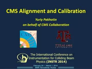
Hardware-based CMS Alignment
Hardware-based CMS Alignment. Iván Vila on Behalf of CMS alignment group Instituto de Física de Cantabria [CSIC-UC]. Outline. Introduction Tracking at CMS The alignment task Steps toward a Hardware alignment. Alignment subsystems overview Inner tracker Global alignment: Link system

Hardware-based CMS Alignment
E N D
Presentation Transcript
Hardware-based CMS Alignment Iván Vila on Behalf of CMS alignment group Instituto de Física de Cantabria [CSIC-UC]
Outline • Introduction • Tracking at CMS • The alignment task • Steps toward a Hardware alignment. • Alignment subsystems overview • Inner tracker • Global alignment: Link system • Muon spectrometer: Barrel, Endcap • Initial Magnet Test and Cosmic Challenge “lessons” • Summary and conclusions Thanks to Bruno, Martin, Pablo, Vladimir and Zoltan for their help and plots Cern Align Workshop, CERN Sept '06, I. Vila
Introduction – CMS Tracking • Range of expected Motions: • ~1-3 cm from B on/off • < 500 T and humidity • Hard radiation environment • Photons, neutrons, charged hadrons • Dose: 1- 100 x 103 Gy ( 10 years ) • Fluence 5 x 10 10 - 2 x10¹⁴ n/cm2 (10 years) Radiation • 4 Teslas • Gradients up to 600 Gauss/cm • Complex field map ~20 m Magnetic Field ~100m ~75-150 m Cern Align Workshop, CERN Sept '06, I. Vila
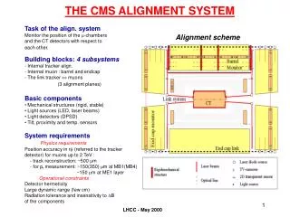
Introduction – Alignment Overview • Hardware alignment (position monitoring) tasks: • Silicon tracker internal alignment • Muon spectrometer internal alignment: • Barril zone • EndCap zone • Global alignment: Relative positioning of TK wrt Muon spectrometer • Link system. • Different geometries, tracking technologies, requirements 4 systems based on different technologies. Cern Align Workshop, CERN Sept '06, I. Vila
Intro. Common road map to Hw align. Design modification System Design Selection/calibration of components/devices Assembly/mounting/fiducialization of components on “rigid” supporting structures Installation and adjust of the system in the detector Geodesy grids, photogrametry and other metrology technologies are a must Thanks to CERN TS-SU Survey Group Cern Align Workshop, CERN Sept '06, I. Vila
TK local Alignment – LAS system TID and Pixel not in LAS! AR: Alignment ring BS: Beam Splitter AT: Alignment tube Cern Align Workshop, CERN Sept '06, I. Vila
LAS - Advantages • Main advantages: • Particle tracks and laser beam share the same sensors removing the need of any mechanical transfer. • Minimum interference with Silicon support structures • No precise positioning of the aiming of the collimators. The number of measurements has to be redundant enough AMS I Align. System Cern Align Workshop, CERN Sept '06, I. Vila
LAS – Optical treatement of sensors Strip direction • 10 mm hole in aluminum backside coating • All sensors with anti-reflective coating Transmission measured to be 14-20% (R4) and13-18% (R6)(at λ=1075 nm) • Reflectivity <= 6% transmission reflection Cern Align Workshop, CERN Sept '06, I. Vila
LAS – Collimators/splitters c Colinearity of laser beams meas. at 50mRad Cern Align Workshop, CERN Sept '06, I. Vila
LAS – Performance @ TEC integration Ring 4 Beam Profiles for Disc 2 and Disc 6 Ring 6 Beam- Splitters Laser pulses RMS of Residuals in first Sector: <70μm Reproduceability: 10μm Cern Align Workshop, CERN Sept '06, I. Vila
ME1/2 Zone Zona ME1/1 Global Alignment – Link System Laser-based Multipoint monitor Links MAB – AR & TK-ME1 Beam Laser MAB MAB X 6 ME/1/3 MAB Zone ME/1/2 YN1 Zone ME1/1 Transfer =3 Zone Tracker Zone ME/1/1 Distance tube Laser source Laser Source AR Link Disk ALING. RING Distance tube Cern Align Workshop, CERN Sept '06, I. Vila
Link – AR / TEC integration MTCC Configuration (shorter TK support tube) CF pillar attached directly to Disk 10 (outside the cold mass and tension-free suport design) 3D relative position of AR wrt silicon supports of disc 10 are measured in Aachen Cern Align Workshop, CERN Sept '06, I. Vila
Coordiante Y Coordiante X Link – Semitransparent ASPD sensors • At lot of R&D on amorphous silicon semitransparent sensors • Improved version based on previous “ALMY” sensors for Atlas muon alignment Deflex ~few mRads Deflex ~Tens of mRads Used as a tool at the geodesic grid for calibration too! Cern Align Workshop, CERN Sept '06, I. Vila
AR-L6 AR-L1 AR-L5 AR-L2 AR-L3 AR-L4 Link Calibration geodesic network AR+ LD + Calibration bench 1:1 scale Cern Align Workshop, CERN Sept '06, I. Vila
Muon Barrel Local Alignment Highly reduntant triangulation measurement. LED sources installed in the muons chambers monitored by Video cameras located in rigid CF structures (MAB) CCD’s muon chambers MAB light sources (LED) Cern Align Workshop, CERN Sept '06, I. Vila
Muon Barrel – Calibration challenge • ALL muon chambers are instrumented and monitored • Thousands of components are to be installed and “calibrated” before installation… Cern Align Workshop, CERN Sept '06, I. Vila
Muon barrel second challenge • Recognition of real vs. reflected LED spots This is a real image taken on forks installed on a chamber. Larger dots belong to the closer fork, while smaller dots are spots of the farther fork. Inside the red markers the real spots can be seen. All the other spots are reflections. Cern Align Workshop, CERN Sept '06, I. Vila
Bias > 2mm Barrel – First “results” • Event before starting… wire layer “SL3” nominal location from calibration. Cern Align Workshop, CERN Sept '06, I. Vila
Muon EndCap Local Alignment • Straight line monitors + potentiometers network Cern Align Workshop, CERN Sept '06, I. Vila
Muon Endcap – “Transparent” sensors • Crosshair laser beam + CCD window frame Cern Align Workshop, CERN Sept '06, I. Vila
Muon Endcap – Hardrad CCD? Cern Align Workshop, CERN Sept '06, I. Vila
75º Barrel Link Magnet Test and Cosmic Challenge a.k.a MTCC • Let’s switch the magnet on and see how things move: Very significant fraction of all the muon alignment system commissioned. Aims: • System Commissioning (Hard & Control) • Check Detector Assembly Tolerances & field effects vs system dynamic range • Monitor Iron deformation (endcap disks) • Extract initial CMS geometry from B = 0 T (Optical & Cosmic) • Compare Cosmic data vs optical alignment (@ B: 0 and max field) Cern Align Workshop, CERN Sept '06, I. Vila
MTCC aftermath (very, very preliminary) • What we have learn ? • How (some)things move (next) • How (not) to install/adjust some of the components. • The actual help (accuracy) we can expect from survey at field B=0. • Installation tolerances far from promised in some cases. • What we have encounter? • “Anticipated” issues (not all of them solved). • Crashes when closing the yokes. • Difficult adjustments of components. • Non anticipated issues (sensitivity to B of electronics.) Cern Align Workshop, CERN Sept '06, I. Vila
MTCC – First results/observations • Track vs. Muon chamber Survey (Sector 10) • Real time monitoring of Iron yoke movements vs. magnetic field. Cern Align Workshop, CERN Sept '06, I. Vila
Summary • Hardware alignment systems extremely complex ( thousands of r/o channels) • Large collaborative effort (Atomki, CERN, Ciemat, Fermilab, Florida, Cantabria, RWTH, University of Debrecen…) • Many ad-hoc solutions & innovative developments. • This is just a very coarse overview…precision is in the details. • First performances under real fire (MTCC) tell as that we are in the right track toward a “Fast” alignment, BUT there is still a long way to go… . Cern Align Workshop, CERN Sept '06, I. Vila
BackUp Cern Align Workshop, CERN Sept '06, I. Vila
Introduction – Main Technologies • Local TK alignment: • Gaussian profile laser lines monitored with optically treated microstrips detectors. • Local alignment of m-spectrometer (Barril): • LED placed on chambers and monitored by video cameras on very rigid FC structures • Local alignment of m-spectrometer (EndCap): • Cross-hair laser profiles monitored by ccd frames on top of the chamber covers. • Global alignment: • Gaussian profile laser lines monitored by custom made semitransparent PSD sensors on top of rigid FC structures. Cern Align Workshop, CERN Sept '06, I. Vila
Alignment systems - The challenges • Barril Muon spectrometer: • 240 chambers to be monitored directly with a few hundred microns precision • End Cap Muon spectrometer: • Precision better than a few hundreds of micron. • Global alignment: Link system • Linking the TK and m-spectrometer reference frames with a few hundred microns and tens of microRads. Cern Align Workshop, CERN Sept '06, I. Vila