Comprehensive Water System Design for the Priesthood Restoration Site
This project focuses on the design of a water system for the Priesthood Restoration Site near Oakland, PA, which is undergoing expansion with a new meetinghouse and facilities. The project addresses the system demands, including fire flow requirements, and proposes solutions such as a 40,000-gallon fiberglass water storage tank. Detailed analysis of pipe sizing, pump selections, and site layout considerations ensure the system meets the needs of visitors and residents while maintaining efficiency and reliability. Cost estimates for the entire project are also included.

Comprehensive Water System Design for the Priesthood Restoration Site
E N D
Presentation Transcript
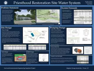
Priesthood Restoration Site Water System Brandon Corbett Blake Newbold Justin Relitz Problem Statement Site Design System Demands Pumping Design The LDS Church has many historic sites around the world which it maintains and improves to all of its visitors. One of the sites is the Priesthood Restoration Site, which is located nearOakland, PA. There is a new meetinghouse being built (rendering shown to the right), a small bathroom, and a triplex that will need a new water system to supply water for visitors and tenants living in the triplex. We were tasked with designing the water system for the site (proposed site layout shown to the right) and all of the elements needed for the system. Given the system demands for the whole project, the demand summary to the right was created. The operating hours were estimated to come up with the average daily demand. Shown in the summary is the average daily demand including and not including the fire flow. As can be seen, the majority of the demand for this system comes from the fire flow required. These calculations were used to find an appropriate tank size and necessary pumping rate to fill the storage tank from the well. Visitor’s Center Rendering (Viewed from Pump Station) System Demands to Calculate Tank Size and Necessary Pumping Rate Priesthood Restoration Site Proposed Site Layout CMU Pump Station Pipes Design There were a total of five pipes that were designed for the system. Analysis of the correct pipe sizes, using the flow demandsshown in the Tables below, was done using EPA-NET. Head loss was calculated using the Hazen-Williams equation and results are shown in the Tables below. HDPE pipes were chosen because of the ease of installation compared to PVC pipes. The pipe sizes range from 2 to 4 inchesin diameter. A site plan showing the locations of pipes is shown in the Figure to the right. The Tables below show the parameters used for each pipe and produced results showing pressures at each junction, total head loss, and velocities in each pipe. The pressures at the five junctions range from 50 to 74 psi and total head loss ranges from 0.15 to 23 feet. The highest head loss occurs because of the fire flow needed for the system. The pump station was designed using 8 inch split face CMU. The corner joints will use 16 inch architectural stone placed every two courses. Located within the pump station will be the pumps for distributing the culinary, irrigation, and fire flow water. It will also house the water treatment system, and provide additional maintenance storage. For ease of installation, or maintenance on the pumps, large 4 foot exterior doors were utilized. This eliminates the need for the pumps to be installed by means of an overhead crane. The roof will be constructed using prefabricated steel trusses, and 29 gauge tin roofing panels. Other features of the pump station include exterior lighting, and a venting system. Site Layout Pump Station Elevations and Floor Plan Pump Selection Using the system demands, and calculated head losses, pumps for each application were chosen. Redundancy for each pump was also designed. Two culinary/irrigation pumps will operate in parallel, thus prolonging the lifetime of each pump. In the event of maintenance or temporary shutdown of one pump, the other will be fully capable of supplying the demand while the other receives repairs, or is replaced. The fire flow pumps will not need to operate in parallel, but a second pump will be installed and used as an immediate backup for the first. Pipe Parameters Pipe Design Results Tank Design Well Design Based on the geotechnical report, the well was designed to use a 40 foot, 12 inch steel casing. From observation wells, the expected flow from the well was estimated. Using this information, the submersible pump was selected. To prevent possible surface water contamination, at least 30 feet of casing should be grouted, with the final 10 feet of casing being surrounded with gravel. The expected yield from the well will be 10 gallons per minute. The water storage tank for the system was required to be underground. With this requirement, the two possible options for tank material were fiberglass and concrete. Due to the vast amount of labor required for a concrete tank, fiberglass was chosen. The tank will be a 40,000 gallon fiberglass tank manufactured by Xerxes. The drawing to the right shows a cross section of the tank and connection to the pump station. Berkeley Pump for Fire Flow (30 HP) and Pump Performance Curve Project Cost Estimate This cost estimate is a summary of the total cost from each part of the project. A complete cost breakdown for each of these parts is contained in the project report. The estimate is based off of material and product costs and does not include costs from labor. With the inclusion of a 15% engineering fee and 25% contingency to cover risk, the total cost comes out to be approximately $280,350. Xerxes Fiberglass Tank Well Design and Soil Profile Material and Engineering Costs Brigham Young University – Provo, UT Civil and Environmental Engineering Capstone Project