Using the Hybrid- p Model
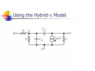
Using the Hybrid- p Model. r bb and r o are omitted (insignificant) R B represents parallel combination of R B 1 and R B 2 At high frequencies C 1 , C 2 and C 3 approximate short circuits. Problem : C BC influences the input and output halves of the circuit.

Using the Hybrid- p Model
E N D
Presentation Transcript
rbb and ro are omitted (insignificant) • RB represents parallel combination of RB1 and RB2 • At high frequencies C1, C2 and C3 approximate short circuits. • Problem : CBC influences the input and output halves of the circuit
Extending the Upper Cut-Off • Use a different transistor – lower CBC. • Reduce the gain; CIN is proportional to gain. • Reduce the source resistance. • Eliminate the Miller effect – use a different amplifier configuration.
Common-Base Configuration Common-emitter amplifier Common-base amplifier
Common-Base Quiescent Conditions i.e. exactly the same as common emitter amplifier.
Common-Base Voltage Gain i.e. same as C-E but non-inverted.
High Frequency Effects • Neither CBC or CBE connects vin to vout. • There is, therefore, no Miller effect. • Cin = CBE • Cout = CBC
C-B vs. C-E Comparison • Identical quiescent conditions • Identical voltage gain (except C-E inverts) • Identical output resistance • Common-Base input impedance is very low • Common-Emitter suffers Miller effect
Summary • Common-emitter upper cut-off frequency is disappointingly low due, mainly, to the Miller effect. • Common-base configuration does not suffer Miller effect but has impractically low input impedance. • Solution : combine the two ?