Download
1 / 85
1.07k likes | 1.63k Vues
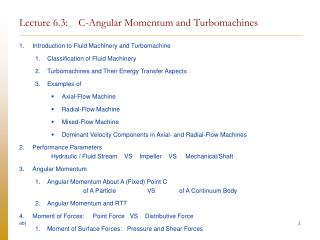
Lecture 6.3: C-Angular Momentum and Turbomachines. Introduction to Fluid Machinery and Turbomachine Classification of Fluid Machinery Turbomachines and Their Energy Transfer Aspects Examples of Axial-Flow Machine Radial-Flow Machine Mixed-Flow Machine

E N D
Lecture 6.3: C-Angular Momentum and Turbomachines • Introduction to Fluid Machinery and Turbomachine • Classification of Fluid Machinery • Turbomachines and Their Energy Transfer Aspects • Examples of • Axial-Flow Machine • Radial-Flow Machine • Mixed-Flow Machine • Dominant Velocity Components in Axial- and Radial-Flow Machines • Performance Parameters Hydraulic / Fluid Stream VS Impeller VS Mechanical/Shaft • Angular Momentum • Angular Momentum About A (Fixed) Point C of A Particle VS of A Continuum Body • Angular Momentum and RTT • Moment of Forces: Point Force VS Distributive Force • Moment of Surface Forces: Pressure and Shear Forces
C-Angular Momentum • C-Angular Momentum (MV) • C-Angular Momentum (CV) • Force, Torque, and Energy Transfer as Work in Turbomachines • Relation between 1) Surface Force (Pressure + Shear) on the Moving/Rotating Impeller Surface2) Energy Transfer as Work at the Impeller Surface, and 3) Impeller Torque and Shaft Torque • Impeller Torque VS Shaft Torque • Euler Turbomachine Equation, Hydraulic Torque, and The Associated Power Equation • Various CV’s and The Corresponding Net/Resultant Moment for Turbomachine Analysis • Euler Turbomachine Equation • Hydraulic Torque • Hydraulic Torque VS Impeller Torque VS Mechanical Torque at Shaft • The Associated Power Equation
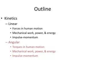
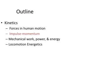
Analysis for The Performance of Idealized Turbomachines • Problem • Blade b (and Flow a) Angles Convention • Sketch the Blade Shape • Shockless-Entry/Exit Condition • Relative Velocity Relation and Velocity Diagram • Is it a pump or a turbine? • Hydraulic Power and Hydraulic Head • In Circular Cylindrical Coordinates r-q-z: Axial-Flow Machine • Basic of Velocity Diagram • Appendix and Review • Recall: The Terminologies: Hydraulic / Fluid Stream VS Mechanical / Shaft • Recall: Free-Body-Diagram (FBD) Concept
Very Brief Summary of Important Points and Equations [1] 1. Euler Turbomachine Equation: 2. The Associated Power Equation: 3. Relative Velocity Relation and Velocity Diagram:
Introduction to Fluid Machinery and Turbomachine
Classification of Fluid Machinery Fluid Machinery Positive Displacement (Confined volume) Dynamic/Turbomachines (Dynamic effect between fluid stream and solid component/rotor) Classification by Direction of Energy Input energy into fluid stream Pump, fan, compressor Extract energy from fluid stream Hydraulic/Wind/Gas/Steam turbine Classification by Direction/Path of Flow (as it passes through the blade passage.) Radial-Flow Mixed-Flow Axial-Flow
1 A fluid stream PE of a fluid stream is extracted and converted to shaft work OUT 2 Centrifugal fan (Radial-flow) http://www.nyb.com/frames/products_fr.htm Hydraulic turbine installation: http://lmhwww.epfl.ch/Publications/Theses/Mauri/thesis_html/node8.html 2 Energy is added to a fluid stream as shaft work IN Low E fluid stream High E fluid stream Streamtube A fluid stream 2 A fluid stream 1 1 High E fluid stream Low E fluid stream KE of a fluid stream is extracted and converted to shaft work OUT http://www.globalenergyequipment.com/ Turbomachines and Their Energy Transfer Aspect Energy extracted from a high-energy fluid stream to be converted to useful shaft work Energy added to a low-energy fluid stream to raise the energy level of the stream
Reference axis q Gas Turbine (Axial Flow) PW-4000 Commercial High Bypass Turbofan Engines (From http://www.aircraftenginedesign.com/pictures/PW4000.gif) c Axial Flow: Blade Rows (From Fluid Dynamics and Heat Transfer of Turbomachinery, Lakshminarayana, B., John Wiley & Son., 1996, p. 9. Photograph courtesy of FIAT.) Axial-Flow Machine • The dominant velocity components are • z (axial) – for carrying the flow through the blade passage/machine, and • q(tangential) – for change in angular momentum torque
Flow through a turbine cascade, outlet Mach number = 0.68 (~ 200 m/s). (From Visualized Flow, The Japan Society of Mechanical Engineers, Pergamon Press, 1988, p.101.) Turbine Cascade (From http://www.sm.go.dlr.de/SMinfo/IADinfo/IAD.html#Projects) A Closer View of Turbine Cascade in Axial-Flow Machine
Duct fan (Axial-flow) (From http://www.nyb.com/frames/products_fr.htm) Wind turbine (From http://www.windpower.org/en/pictures/multimeg.htm)
q c Reference axis Radial-Flow Machine • The dominant velocity components are • r (radial) – required for carrying the flow through the blade passage/machine, and • q(tangential) – required for change in angular momentum torque Centrifugal fan (Radial-flow) (From http://www.nyb.com/frames/products_fr.htm)
Centrifugal pump (From http://www.peerlessxnet.com/documents/8175_Prod.bmp)
Radial/Mixed compressor impeller (From http://turbo.mech.iwate-u.ac.jp/Fel/turbomachines/stanford/images/turbo/radial1.html) Mixed-Flow Machine
Turbocharger (From http://turbo.mech.iwate-u.ac.jp/Fel/turbomachines/stanford/images/turbo/radial6.html)
Axial-Flow Machines Radial-Flow Machines Axial Flow: Blade Rows (From Fluid Dynamics and Heat Transfer of Turbomachinery, Lakshminarayana, B., John Wiley & Son., 1996, p. 9. Photograph courtesy of FIAT.) q (tangential) required for change in angular momentum torque n (normal) required for carrying the flow through the blade passage/ machine. Radial Flow (Centrifugal fan) (From http://www.nyb.com/frames/products_fr.htm) Dominant Velocity Components in Axial- and Radial-Flow Machines
Performance Parameters Hydraulic / Fluid Stream VS Impeller VS Mechanical/Shaft
Impeller Power Shaft Power Hydraulic Power 1 1 2 2 1 2 Properties of fluid stream, not those of solid shaft, e.g., pressure p of fluid, velocity V of fluid, etc. Impeller work [Mechanical] Energy transfer as work (between the moving solid impeller and the fluid stream) at the moving solid impeller surface. (Solid-Fluid Interaction] Shaft Work [Mechanical] Energy transfer as work (between one part of the solid shaft to another part of the solid shaft) at the solid cross section of a shaft. Hydraulic Power The actual amount of mechanical energy me that the fluid stream receives/gives up from inlet 1 to exit 2. Recall: Hydraulic Power VS Impeller Power VS Mechanical Power at Shaft [See also Appendix and Review: Recall The Terminologies: Hydraulic / Fluid Stream VS Mechanical / Shaft ]
Performance Parameters With the intended uses of turbomachines, the following performance parameters are of interest. [See summary next slide.] • Torque input (pump, fan, etc.) or torque output (turbine, etc.) • Hydraulic Torque VS Impeller Torque VS Mechanical / Shaft Torque • Power input/output. • Hydraulic Power VS Impeller Power VS Mechanical/Shaft Power • Other parameters of interest are, e.g., • flowrate, • hydraulic head, • total and static pressure rise, • etc. • Recall Terminologies: • Hydraulic/Fluid Stream Quantities • Properties of a fluid stream, • Evaluated from fluid stream properties • Mechanical / Shaft Quantities • Properties of a solid shaft • Evaluated from shaft • See also Appendix and Review: • Recall: The Terminologies: • Hydraulic / Fluid Stream VS Mechanical / Shaft
Mechanical / Shaft Side (subscripteds) Hydraulic / Fluid Stream Side (subscriptedh) Torque Hydraulic Torque Shaft Torque Power Hydraulic Power Shaft Power Head Hydraulic Head Euler Turbomachine Equation: (for idealized machines) = Hydraulic torque x shaft angular velocity (mixed quantity) Associated Power Equation: Summary of Important Quantities: Hydraulic / Fluid Stream VS Mechanical/Shaft
m y y Observer A Observer A x x C C Angular Momentum About A (Fixed) Point C of A Particle VS of A Continuum Body Particle Continuum body • Angular momentum of a body about a point c is defined as the moment of linear momentum of the body about the point c.
MV(t) and CV(t) y Observer A x C Reynolds Transport Theorem (RTT): Angular Momentum and [Recall] The RTT Coincident MV and CV
Example 1: Finding The Time Rate of Change of The Angular Momentum of an MV By The Use of A Coincident CV and The RTT Problem: Given that the velocity field is steady-in-mean and the flow is incompressible, and we evaluate the mean properties. 1. State whether or not the time rate of change of the angular momentum about the z-axis passing through point c (Hc,z) of the material volume MV(t) that instantaneously coincides with the control volume CVshown below vanishes. 2. if not, state also - whether they are positive or negative, and - whether there should be the corresponding net moment (Mz) acting on the MV/CV, and - whether the corresponding net moment is positive or negative. 3. Find it.
c c + + c + tangential exit radial exit r axial inlet + c z y r axial inlet x + c z
Moment of Forces Point Force VS Distributive Force
Point Force Distributive Force C C results in Surface Integral Surface Force: results in Volume Integral Volume Force: Moment of Forces about A Point C: Point Force VS Distributive Force
Surface Integral Volume Integral Because the evaluation of the moment of distributive forces results in It is to be understood that when we simply write we refer to the corresponding surface or volume integral. Surface Force: Volume Force:
c A A C Open surface Closed surface To find the net moment of a surface force (pressure or shear) on an MV, we just simply sum (integrate) it over the whole MS. Moment about c due to pressure force: Moment about c due to shear/frictional force: Note: The shear force – and in fact all the surface forces - can be written in terms of the area vector as where is the stress tensor corresponding to that force. Because it is a little more complicated at this point, we shall leave it at that. Moment of Surface Forces: Pressure and Shear Forces
C-Angular Momentum [ MV ] Here, we shall limit ourselves to an observer in IFR only.
FBD (again) Concentrated force Pressurep Distributive force Sheart c y Solid part Observer A, IFR x = Net/Resultant moment of all external forces/moments(hence, FBD again)on the MV(t) about a fixed point c. C-Angular Momentum [MV] • Physical Law (for an observer in an IFR and a fixed point C)
It is emphasized that in the physical law is the net/resultant moment of all external forces/moments(hence, FBD again)on the MV(t) about a fixed point c. FBD Concept Net/Resultant moment of all external forces/moments (hence, FBD again) on the MV(t) about a fixed point c Recall the FBD Concept In C-Angular Momentum, we need to sum all the external moments of all the external forces/moments about C on the MV,
FBD Concept • FBD Concept • Define the system of interest clearly. • Know and Recognize various types of forces (/moments). • With 2, recognize all forces (/moments) that act on the current system of interest. • Know how to find their • resultant force , and • resultant moment Recall in case of fluid flow: Forces in fluids (or solid – i.e., continuum, - for that matters) • Forces in Fluid: Line Force + Surface Force + Body Force • Surface forces = Pressure/Normal + Friction/Tangential • Need to sum the contributions due to surface forces on all surfaces of the MS.
Pressure p Distributive force in fluid Shear t surface force surface integral Concentrated force Pressure p Shear t c Solid part c Normal p Solid part Shear t Cross section of a solid shaft Normal p Shear t Distributive force in solid • For surface force, we need to sum the contributions of surface forces over all surfaces of MV, and both solid and fluid parts. • For solid part, p refer to normal stress and it must also be included in • Recognize that is in fact the resultant moment/couple of shear stress (surface force) distribution over a cross section of a solid shaft. Examples
Thus, depending on the forces and moments that act on the current system of interest, the specific form for depends on that specific force/moment system. • According to the physical law of C-Angular Momentum (hence, FBD) • = sum of all external moments due to all external forces/moments on MV • Generically, though, we may simply write • or even • to emphasize the distributive nature of forces in fluid. • However, for example, if there are concentrated forces on the MV, it is to be understood that all these forces must be taken into account in , e.g., Note on Notations
Pressure p Concentrated force Distributive force Shear t c • Physical Law (for an observer in IFR and a fixed point C) • RTT Solid part MV(t) CV(t) Physical Laws • C-Angular Momentum RTT C-Angular Momentum [CV] Coincident MV(t) and CV(t)
According to the Energy-Work Principle: A moving solid body in a fluid stream (in this case, a moving/rotating solid impeller) is required in order to have energy transfer as work between the solid body and the fluid stream. Force results in Torque Force results in Energy Transfer as work Impeller and shaft as a system Relation between 1) Surface Force (Pressure + Shear) on the Moving/Rotating Impeller Surface2) Energy Transfer as Work at the Impeller Surface, and 3) Impeller Torque and Shaft Torque Centrifugal fan (Radial-flow, from http://www.nyb.com/frames/products_fr.htm)
c • Note that • shaft torque, and • 2. impeller torque, • are related through the FBD of the section of the solid impeller as shown. • However, they are generally not equal due to, e.g., frictional torque, at the bearings . z Impeller Torque VS Shaft Torque Impeller Torque defined as the net moment due to surface force on the impeller
Euler Turbomachine Equation, Hydraulic Torque, and The Associated Power Equation
1 1 z c z c 2 Moving solid impeller surface (Recall the outward normal to the system of interest) 2 = Shaft torque Various MV/CV’s and The Corresponding Net/Resultant Moment for Turbomachine Analysis CV2/MV2: CV includes fluid stream only, no solid part. CV1/MV1: CV includes fluid stream, impeller, and part of solid shaft Recall the concept of FBD Shaft torque for CV1/MV1 No shaft torque for CV2/MV2
2 z 1 2 View this way r1 1 c at solid shaft cross section Example 1: Radial-Flow Machines [1] Centrifugal fan (Radial-flow) (From http://www.nyb.com/frames/products_fr.htm) Inlet 1 = Inner cylindrical surface Exit 2 = Outer cylindrical surface CV/MV: CV includes fluid stream, impeller (and its back plate), and cuts across the solid shaft at the back plate.
Note on Notations • To avoid messy diagram, it is to be understood that • to evaluate , all moments due to all forces must be taken into account. • For surface forces, need to sum the surface forces on all surfaces of the MS/CS • Surface forces = Pressure/Normal + Friction/Tangential • Hence, to remind us once in a while or to focus on some surfaces, we shall simply use the figure of • the area vector or simply in place of the more complete one • and only on some surfaces instead of on all surfaces.
We can also include the fluid stream only. • This time we will not see the shaft torque • But we see instead additional forces (pressure and shear) on the impeller surface (fluid as a system) whose moment must be taken into account in and . 2 2 1 1 r1 r1 Example 1 CV/MV CV/MV: CV includes fluid stream only, no solid part. Example 2: Radial-Flow Machines [2] For clarity, forces on other surfaces are omitted from the diagram.
View this way z z 2 1 View this way c c r1 CV/MV: CV includes fluid stream, impeller (and its back plate), and cuts across the solid shaft at the back plate. It also includes part of the axial inlet duct. Inlet 1 = Inlet duct circular cross section Exit 2 = Outer cylindrical surface Example 3: Radial-Flow Machines [3] [Compare to Example 1]
A single blade z c Annular exit plane Annular inlet plane Example 4: Axial-Flow Machines CV covers the whole rotor and cuts through the cross section of a solid shaft. Note, however that the inlet and exit planes are annular. Turbine Cascade (From http://www.sm.go.dlr.de/SMinfo/IADinfo/IAD.html#Projects)
2 1 r1 1 z c 2 Euler Turbomachine Equation Coincident MV(t) and CV(t) z CV/MV includes fluid stream, impeller, part of solid shaft, and inlet and exit ducts. It cuts across a cross section of the solid shaft. This CV illustrates the global nature of the Euler Turbomachine equation - without having to deal with the blade geometry, i.e., torque = net angular momentum efflux. CV/MV [CV in Example 1] includes fluid stream, impeller (and its back plate), and cuts across a cross section of the solid shaft (and no inlet and exit ducts). Later, this CV is used in developing the associated power equation.
1 z c 2 • Assumptions • All flow properties are steady in mean. • Evaluate mean properties. • Incompressible flow • Neglect all other torques, except shaft torque. • [Neglect torques due to surface force (pressure + shear), body force (mg), frictional torque at bearings, etc.]. • C-Angular Momentum
2 1 Unsteady Term: r1 1 Net Convection Efflux Term: Net Moment about c: z c Euler Turbomachine Equation: 2 C-Angular Momentum becomes
Euler’s Turbomachine Equation: Hydraulic Torque [CV Viewpoint] = Net convection efflux of angular momentum through CS. Hydraulic Torque [MV Viewpoint] Hydraulic Torque: = the time rate of change of angular momentum of the fluid stream as it flows through CV [from CV inlet 1 to CV exit 2]. Hydraulic Torque In a similar manner as hydraulic power, we define the RHS (and the RHS only) as the hydraulic torque. Like hydraulic power, through the RTT, we can see that the two views are equivalent.