Download
1 / 38
380 likes | 479 Vues
This final project presentation outlines an innovative autonomous convoy control system using path-following algorithms and multiple asynchronous nodes. Developed for military convoy applications, the system reduces human requirements and serves as a supplement to existing navigation systems. It offers an alternative to complex inter-vehicle communications through a proof of concept prototype featuring Autonomous Convoy Vehicles (ACVs) with a modular, passive operation design. The cost-effective system integrates various components like the Nintendo Wii Sensor Bar and IR emitters for precise tracking. The project overview covers the VHDL system block diagram, odometry and coordinate system, waypointed path-following strategy, waypoint queue maintenance, and acceptance testing.

E N D
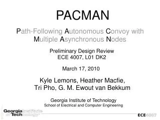
PACMAN Path-Following AutonomousConvoy with Multiple Asynchronous Nodes Final Project Presentation ECE 4007, L01 DK2 April 26, 2010 Kyle Lemons, Heather Macfie, Tri Pho, G. M. Ewout van Bekkum Georgia Institute of Technology School of Electrical and Computer Engineering
Project Overview • Military convoy applications • Reduction of human requirements • Supplement to existing navigation systems • Alternative to complex inter-vehicle communications • Proof of Concept Prototype • Autonomous Convoy Vehicles (ACVs) • Path-follow Algorithm • Modularity • Passive Operation • Cost: $450
Final Design Battery Bay Photo-Reflectors Steering Servomechanism Motor
Final Design Altera DE2 FPGA Development Board
Final Design Electronic Speed Control
Final Design I/O Daughter Board
Electronic Speed Control Final Design Steering Servomechanism Left Photo-Reflector Right Photo-Reflector
GPIO to Altera DE2 FPGA Development Board Final Design
Final Design Nintendo Wii Sensor Bar
Final Design IR Band-pass filter
I/O Daughter Board • Interface between the FPGA and the rest of the system • Photo-Reflector circuit including analog to discrete conversion for odometry • Bidirectional 3.3v to 5v level shifting • IR Camera array with 35 degrees between cameras
IR Camera Array • Mounted three infrared cameras taken from Nintendo's Wii Remote • Slightly overlapping field of view between cameras results in an overall system horizontal FOV of 105 degrees
IR Emitter Bar • Purchased after-market Sensor Bars • Poor angular response resulted in unreliable tracking when not straight to the camera • Ambiguity arose since the sensor bar could be interpreted as two or four blobs • Custom machined sensor bars with extra angled LEDs • Distance between IR LEDs was not sufficient to be reliably tracked at far distances • Borrowed the more expensive official Nintendo branded sensor bars from peers
Odometry and Coordinate System • Rollover is not a concern as millimeter precision still allows for an operating range of more than 4000 kilometers in either axis Decided to maintain an absolute non-moving coordinate system in the odometry module. Origin is fixed at midpoint of the rear axle of the car's initial position
Waypointed Path-following • Waypoints to the preceding vehicle are generated by calculating their relative displacement in the absolute coordinate system • Compensation for the disparity between rear wheel axle and camera position uses orientation information from the odometry module
Waypointed Path-following • Waypoints to the preceding vehicle are generated by calculating their relative displacement in the absolute coordinate system • Compensation for the disparity between rear wheel axle and camera position uses orientation information from the odometry module
Waypointed Path-following • Waypoints to the preceding vehicle are generated by calculating their relative displacement in the absolute coordinate system • Compensation for the disparity between rear wheel axle and camera position uses orientation information from the odometry module
Waypointed Path-following • Waypoints to the preceding vehicle are generated by calculating their relative displacement in the absolute coordinate system • Compensation for the disparity between rear wheel axle and camera position uses orientation information from the odometry module
Waypoint Queue • Queue maintains: • Waypoints • Current ACV position • Total sum of all waypoints • Relative coordinates • Waypoints relative to previous • Current relative to last passed • Absolute coordinates • Reads from odometry • Calculates and uses deltas • Ignores overflow
Adding Future Waypoints • Given: • Sum of waypoints • Current position • Position of LED bar • Calculate: • Vision - QueueSum + Current • Add to end of queue
Waypoint Steering and Throttle Control • Compare current and first waypoint output from queue • Gives distance and angle • Constantly updated • Steers using linear approximation • Deadband in center • Configurably aggressive turns • Throttle gets "kickstart" and returns • Overcome momentum requirement • Sustain slower speed
Waypoint Queue Maintenance • Approaching next waypoint • Linear distance approximation • Drops waypoint early • Avoids unstable turning angles • Minimum waypoint sum for following • Linear distance approximation • Disables output to ESC • Avoids collisions
Acceptance Testing Overview • Path-following • Max deviation from path • Using a fixed set of waypoints, test runs show ACVs pass over waypoints • Follow distance • Images captured from test runs using known distances to verify actual following distance • Turning radius • Driving the lead vechicle around a turn and observing the ACV following performance • Modular ACVs • Placing multiple ACVs in a line and driving the lead vehicle while observing following behavior
Objectives • Path-following • Follow distance: <200 cm • Max deviation from path: <10 cm • Autonomous operation • Speed: >40 cm/s • Turning radius: <200 cm • Passive operation • Modular ACVs
Objectives and Achievements • Path-following • Follow distance: <200 cm ~98 cm • Max deviation from path: <10 cm ~9 cm • Autonomous operation • Speed: >40 cm/s ~60 cm/s • Turning radius: <200 cm ~133 cm • Passive operation • Modular ACVs
Objectives and Achievements • Path-following • Follow distance: <200 cm ~98 cm • Max deviation from path: <10 cm ~9 cm • Autonomous operation • Speed: >40 cm/s ~60 cm/s • Turning radius: <200 cm ~133 cm • Passive operation • Modular ACVs Demonstrate the feasibility of an autonomous path-following system
Future Work • Integration of system into a full-scale convoy • Improvements to hardware during full-scale conversion • More accurate and flexible odometry, such as optical flow • More capable vision system • More robust processing unit, including a floating point unit and a trigonometry unit