
Electromagnetic Induction
E N D
Presentation Transcript
Electromagnetic Induction AC Circuits and transformers
Effective Current • Emf in ac circuits is equivalent to potential difference in dc circuits • Resistance, current, and emf can all be measured using a multimeter • Induced emf as a function of time = maximum emf * sine of the angular frequency of rotation * time • Δv = Δvmax * sinω * t • Instantaneous current = maximum current * sine of the angular frequency of rotation * time • i = Imax* sinω * t
Effective Current • Since alternating current is constantly reversing, maximum current and emf values are not as useful as they are in direct current • Of more importance are instantaneous and root-mean-square (rms) values • Rms current – the amount of direct current that dissipates as much energy in a resistor as an instantaneous alternating current does during a complete cycle • - the value of alternating current that gives the same heating effect that the corresponding value of direct current does • An equivalent value allowing for accurate comparisons between alternating and direct current • Power can be calculated by using the appropriate rms values in the equations given previously
Effective Current • Power = rms current squared * resistance • Power = one-half * maximum current squared * resistance • P = (Irms)2R = ½(Imax)2R • Ohm’s law still applies in ac circuits • Rms potential difference = rms current * resistance • Vrms = Irms*R
Effective Current • Sample problem: A generator with a maximum output emf of 205V is connected to a 115 resistor. Calculate the rms potential difference. Find the rms current through the resistor. Find the maximum ac current in the circuit. • Vmax = 205V R = 115 • Vrms = ? Irms = ? Imax = ? • Vrms = .707*Vmax • Irms= Vrms / R • Irms = .707*Imax
Effective Current • Resistance influences current in an ac circuit • The ac potential difference (ac voltage) measured in an electrical outlet is a rmsemf with a value of 120V • Maximum emf value for an outlet is about 170V • Ammeters and voltmeters (and therefore multimeters) that measure alternating current are calibrated to measure rms values for current and emf (voltage)
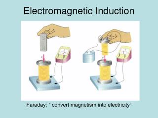
Transformers • Transformer – a device that increases or decreases the emf of alternating current • In its simplest form, a transformer consists of two coils of wire wrapped around an iron core • The first coil, or primary or input coil, is connected to a voltage source • The second coil, or secondary or output coil, is connected to a resistor or other load • The relative number of times the coils are wrapped around the iron core determines what happens to the voltage • If the primary coil has more loops, the voltage decreases • Step-down transformer • If the secondary coil has more loops, the voltage increases • Step-up transformer
Transformers • Transformer Equation • Induced emf in secondary coil = (number of turns in secondary coil) / (number of turns in primary coil) * applied emf in primary coil • ΔV2 =N2 / N1 * ΔV1 • Can’t have something for nothing • Due to energy loss due to heating and radiation, so the output power will be less than the input power • Any increase in voltage must be offset by a proportional decrease in current • Real transformers have efficiency values of 90-99% • To minimize power lost by resistive heating (I2R loss) in transmission lines, electric lines have high emf values and low currents • Main lines have emf = 230000V • Regional lines have emf = 20000V • Customer lines have emf = 120V
Transformers • Transformers
Transformers • The ignition coil in a gasoline engine is a transformer • Changes 12 dc V into an emf of 100000V to ignite and burn fuel when sparkplug fires • Crank angle sensor detects the crankshafts position to determine when the engine cylinder’s contents are at maximum compression