Download
1 / 59
630 likes | 926 Vues
Image Processing. Introduction to Image Processing. Cameras, lenses and sensors. Cosimo Distante Cosimo.distante@cnr.it Cosimo.distante@unisalento.it. Cameras, lenses and sensors. Camera Models Pinhole Perspective Projection Camera with Lenses Sensing The Human Eye.

E N D
Image Processing Introduction to Image Processing Cameras, lenses and sensors CosimoDistante Cosimo.distante@cnr.it Cosimo.distante@unisalento.it
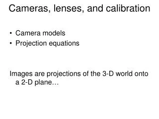
Cameras, lenses and sensors • Camera Models • Pinhole Perspective Projection • Camera with Lenses • Sensing • The Human Eye
Images are two-dimensional patterns of brightness values. Figure from US Navy Manual of Basic Optics and Optical Instruments, prepared by Bureau of Naval Personnel. Reprinted by Dover Publications, Inc., 1969. They are formed by the projection of 3D objects.
Animal eye: a looonnng time ago. Photographic camera: Niepce, 1816. Pinhole perspective projection: Brunelleschi, XVth Century. Camera obscura: XVIth Century.
Parallel lines meet • vanishing point
Vanishing points VPL H VPR VP2 VP1 To different directions correspond different vanishing points VP3
Geometric properties of projection • Points go to points • Lines go to lines • Planes go to whole image or half-plane • Polygons go to polygons • Degenerate cases: • line through focal point yields point • plane through focal point yields line
X Image plane P=(X,Z) f P=(x,f) Optical axis O Z Pinhole Camera Model X x
Y Image plane P=(Y,Z) f P=(y,f) Optical axis O Z Pinhole Camera Model Y y
Pinhole Perspective Equation Image plane Focal length Optical axis Camera frame Scene / world points
Affine projection models: Weak perspective projection is the magnification. When the scene relief is small compared its distance from the Camera, m can be taken constant: weak perspective projection.
Affine projection models: Orthographic projection When the camera is at a (roughly constant) distance from the scene, take m=1.
Planar pinhole perspective Orthographic projection Spherical pinhole perspective
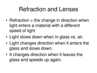
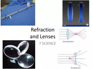
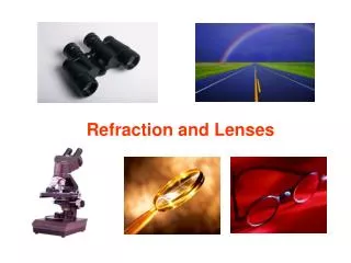
Lenses Snell’s law n1 sina1 = n2 sin a2 Descartes’ law
Twoparameterscharacterize an opticalsystem • focallenghtf • Diameter Dthatdetermines the amount of light hitting the image plane Parameters of an optical system . F focal point optical center (Center Of Projection)
Relative Apertureis the ratio D/f Its inverse isnameddiaphragm aperture a,definedas: a = f/D f/# The diaphragmis a mechanism to limit the amount of light throug the opticalsystem and reaching the imagplanewherephotosensors are deposited (i.e CCD sensor) The diaphragmiscomposed of manylamellaehinged on a ring which rotate in a synchronizedmanner by varying the size of the circular opening, thuslimiting the passage of light Parameters of an optical system . F Diaphragm
Aperture scale varies with square of first value is 1 Other values are 1.4, 2, 2.8, 4, 5.6, 8, 11, 16, 32, 45, 60, … Parameters of an optical system Normally an opticalsystemisdinamicallyconfigured to project the right amount of light, by compensating with the exposure time .
Parameters of an optical system 35mm set atf/11, Aperture varies from f/2.0 to f/22 .
Lens field of viewcomputation Lens choisedepend on the wantedacquired scene. Per le telecamere con CCD 1/4”Focal lenght (mm) = Target distance (m.) x 3,6 : width (m.) Per tutte le altre telecamere con CCD 1/3"Focal lenght (mm) = Target distance (m.) x 4,8 : width (m.)
Focus and depth of field f / 5.6 . f / 32 • Changing the aperture size affects depth of field • A smaller aperture increases the range in which the object is approximately in focus Flower images from Wikipedia http://en.wikipedia.org/wiki/Depth_of_field
Depth from focus Images from same point of view, different camera parameters 3d shape / depth estimates [figs from H. Jin and P. Favaro, 2002]
Field of view • Angular measure of portion of 3d space seen by the camera Images from http://en.wikipedia.org/wiki/Angle_of_view K. Grauman
Field of view depends on focal length • As f gets smaller, image becomes more wide angle • more world points project onto the finite image plane • As f gets larger, image becomes more telescopic • smaller part of the world projects onto the finite image plane from R. Duraiswami
Field of view depends on focal length Smaller FOV = larger Focal Length Slide by A. Efros
Vignetting http://www.ptgui.com/examples/vigntutorial.html http://www.tlucretius.net/Photo/eHolga.html
Vignetting • “natural”: • “mechanical”: intrusion on optical path
Deviations from the lens model 3 assumptions : 1. all rays from a point are focused onto 1 image point 2. all image points in a single plane 3. magnification is constant deviations from this ideal are aberrations
Aberrations 2 types : 1. geometrical 2. chromatic geometrical : small for paraxial rays study through 3rd order optics chromatic : refractive index function of wavelength
Geometrical aberrations • spherical aberration • astigmatism • distortion • coma aberrations are reduced by combining lenses
Spherical aberration rays parallel to the axis do not converge outer portions of the lens yield smaller focal lenghts
Astigmatism Different focal length for inclined rays
Distortion magnification/focal length different for different angles of inclination pincushion (tele-photo) barrel (wide-angle) Can be corrected! (if parameters are know)
Coma point off the axis depicted as comet shaped blob
Chromatic aberration rays of different wavelengths focused in different planes cannot be removed completely sometimes achromatization is achieved for more than 2 wavelengths
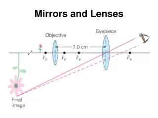
Digital cameras • Film sensor array • Often an array of charge coupled devices • Each CCD is light sensitive diode that converts photons (light energy) to electrons camera CCD array frame grabber optics computer K. Grauman
Historical context • Pinhole model:Mozi (470-390 BCE), Aristotle (384-322 BCE) • Principles of optics (including lenses):Alhacen (965-1039 CE) • Camera obscura: Leonardo da Vinci (1452-1519), Johann Zahn (1631-1707) • First photo: Joseph Nicephore Niepce (1822) • Daguerréotypes (1839) • Photographic film (Eastman, 1889) • Cinema (Lumière Brothers, 1895) • Color Photography (Lumière Brothers, 1908) • Television (Baird, Farnsworth, Zworykin, 1920s) • First consumer camera with CCD: Sony Mavica (1981) • First fully digital camera: Kodak DCS100 (1990) Alhacen’s notes Niepce, “La Table Servie,” 1822 Slide credit: L. Lazebnik CCD chip K. Grauman
Mature technology Specific technology High production cost High power consumption Higher fill rate Blooming Sequential readout Recent technology Standard IC technology Cheap Low power Less sensitive Per pixel amplification Random pixel access Smart pixels On chip integration with other components CCD vs. CMOS
Resolution • sensor: size of real world scene element a that images to a single pixel • image: number of pixels • Influences what analysis is feasible, affects best representation choice. [fig from Mori et al]
Digital images Think of images as matrices taken from CCD array. K. Grauman