Download
1 / 18
350 likes | 1.14k Vues
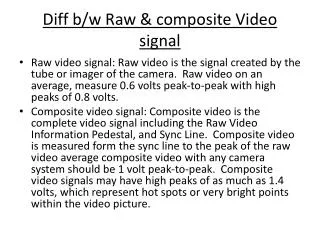
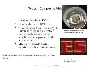
3. COMPOSITE VIDEO SIGNAL. Prepared by Sam Kollannore U. Lecturer, Department of Electronics M.E.S.College, Marampally, Aluva-7. COMPOSITE VIDEO SIGNAL Consist of : . Camera signal - corresponding to the desired picture information Blanking pulses – to make the retrace invisible

E N D
3. COMPOSITE VIDEO SIGNAL Prepared by Sam Kollannore U. Lecturer, Department of Electronics M.E.S.College, Marampally, Aluva-7
COMPOSITE VIDEO SIGNAL Consist of : • Camera signal - corresponding to the desired picture information • Blanking pulses – to make the retrace invisible • Synchronizing pulses – to synchronize the transmitter and receiver scanning -horizontal sync pulse -vertical sync pulse -their amplitudes are kept same -but their duration are different -needed consecutively and not simultaneously with the picture signal – so sent on a time division basis
Composite video signal …contd Video signal varies between certain limits Peak white level: 10 to 12.5% Black level : 72% Blanking level : Sync pulses added - 75% level Pedestal : difference between black level and blanking level – tend to merge Pedestal height : distance between the pedestal level and the dc level – indicates the average brightness Picture information : 10% - 75% Darker the picture – higher will be the voltage within those limits
DC component of the video signal • Average value or dc component corresponding to the average brightness of the scene • Average brightness can change only from frame to frame and not from line to line • Low pedestal height – scene darker • Larger pedestal height – higher average brightness
blanking pulses . . . Make the retrace lines invisible by raising the signal amplitude slightly above the black level (75%) Repetition rate of horizontal blanking pulse = scanning freq. = 15625Hz Freq of vertical blanking pulse = field scanning freq. = 50 Hz
Sync Pulse and Video Signal Amplitude Ratio P/S RATIO = 10/4 Justification: • If the picture signal amplitude is ↑ at the expense of sync pulses – when S/N ratio at the receiver falls, sync pulse amplitude becomes insufficient to keep the picture locked • If the sync pulse amplitude is ↑ at the expense of the picture signal, then the raster remains locked but the amplitude of the picture content will be too low • P/S ratio of 10/4 represents the most efficient use of TV system
horizontal sync details …contd • Total line period = 64µS • Line blanking period = 12µS • Differential leading edges are used for synchronizing horizontal scanning oscillator • Divided into three sections : front porch: 1.5µS - allows the receiver video to settle down line sync : 4.7 µS - for blanking the flyback/retrace - blacker than the black back porch : 5.8µS - time for the horizontal time base circuit to reverse the direction of current for scanning the next line - same amplitude as that of blanking level ; used by AGC circuits at the receiver to develop true AGC voltage
Vertical Sync details …contd. • Added after each fields • Complex in nature • Vertical sync period = 2.5 to 3 times the horizontal line period • In 625 line system: 2.5 × 64 = 160µS • Commence at the end of first half of 313th line (end of first field) and terminates at the end of 315th line • Similarly after an exact interval of 20mS (one field period), the next sync pulse occupies the line numbers 1st, 2nd and first half of 3rd .
Vertical sync details …contd • Horizontal sync information is extracted from the sync pulse train by differentiation i.e. Passing the pulse train through an HPF – leading edges are used to synchronize the horizontal scanning oscillator • Furthermore, receivers often use monostable multivibrators to generate horizontal scan, and so a pulse is required to initiate each and every cycle of the horizontal oscillator in the receiver.
Shortcomings and its solution 1. Horizontal sync pulses are available both during the active and blanked line periods but there are no sync pulses (leading edges) available during the 2.5 line vertical sync period – horizontal sweep oscillator would tend to step out of synchronism during each vertical sync period • The situation after an odd field is even worse -since it begins at midway -leading edge of the vertical sync pulse comes at the wrong time to provide synchronism for the horizontal oscillator • Therefore five narrow slots (4.7µS width) are cut in the vertical sync pulse at intervals of 32µS – rising edges are used to trigger horizontal oscillator. • This insertion of short pulses : called notching of serration of the broad field pulses
Shortcomings and its solution ….contd notching of serration of the broad field pulses notching of serration of the broad field pulses
Shortcomings and its solution ….contd 2. It is seen that the synchronization of the vertical sweep oscillator in the receiver is obtained from vertical sync pulses by integrator (LPF) • Voltage built across the capacitor of the LPF corresponding to the sync pulse trains of both the fields is shown in fig.
Shortcomings and its solution ….contd • Each horizontal pulse cause a slight rise in voltage across the capacitor, but this is reduced to zero by the time the next pulse arrives (charging period=4.7µS and discharging period = 59.3µS) • But during broad serrated region, capacitor has more time to charge and only 4.7µS to discharge • Situation is different for the beginning of the 2nd field-here the last horizontal pulse corresponding to the beginning of the 313th line is separated from the first vertical pulse by only half-a-line. • Therefore the voltage developed a/c the vertical filter will not have enough time to reach zero before the arrival of the 1st vertical pulse • Hence the voltage developed a/c the o/p filter is some what higher at each instant as compared to the voltage developed at the beginning of the 1st field (shown as dotted chain) • i.e. Oscillator get triggered a fraction of a second early as compared to the first field - upset the desired interlacing sequence • Equalizing pulses are used to solve this problem
Equalizing pulses • Solves the shortcomings occurring on account of half line discrepancy • Five narrow pulses of 2.5 line period are added on either side of the vertical sync pulses : known as pre-equalizing and post-equalizing pulses • The effect of these pulses is to shift the half line discrepancy away from both the beginning and end of the vertical sync pulses
Equalizing pulses . . .contd • Pre-equalizing pulses: - 2.3µS duration - result in the discharge of the capacitor to zero voltage in both the fields • Post-equalizing pulses: necessary for a fast discharge of the capacitor to ensure triggering of the vertical oscillator at proper time • With the insertion of equalizing pulses: - the voltage rise and fall profile is the same for both the field sequences - the vertical oscillator is triggered at the proper instants. i.e. exactly at an interval of 1/50th of a second.