
Arduino-Based Monitoring System for Off-Grid Solar and Wind Power Management
This project discusses the implementation of an Arduino microcontroller to monitor and control an off-the-grid power system comprising solar and wind energy sources at the Chews Ridge Observatory. It features a user-friendly interface that leverages a touch screen and web page to facilitate the monitoring of battery voltages and the operation of backup generators. The use of UDP messaging ensures efficient communication between multiple Arduino units, allowing real-time reporting and precise control of power management tasks, thereby enhancing the reliability of the energy system.

Arduino-Based Monitoring System for Off-Grid Solar and Wind Power Management
E N D
Presentation Transcript
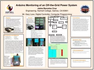
Arduino Monitoring of an Off-the-Grid Power System Jaime Barcelos CruzEngineering, Hartnell College, Salinas, CA 93901 Mr. Gary Love, Digital Controller, Computer Programming Conclusions The Arduino microcontroller is ideal for this type of application. It needs no major programming experience and it has many inputs and output sockets that take digital and analog readings and do work with them. Once readings from analog sensors have been processed and transformed into numbers, the microcontroller can execute several task with much more precision than an analog controller. The self-monitoring routine nested in the main body of the software, is fast enough to detect failures from sensors and report to the user in time for a quick response. UDP packets proved to be very efficient in displaying the status of the generators and maintain communication between Arduinos over the local network. In addition, the step down voltage displayed will also be more accurate because of the quick electrical signals that transmit information to the screen and web page. Thus, the readings will be at real time, reliable, and consistent. Abstract The need to control machines with a microcontroller over a local or global network is a task that goes hand with hand with digital technology. In this project, an Arduino microprocessor, an ethernet shield, and a 2.8” touch screen were programmed and a web page developed to monitor and control a bank of solar and wind charged batteries to power the Chews Ridge Observatory located above Carmel Valley. The finished system starts a back-up generator to maintain minimum power should the solar and wind sources fail. • Results • The two microcontroller communicate via UDP messaging • The web page is design so it communicates with Arduino-master • Generators are easily turn on and off from the comfort of MIRA’s office • With this new technology, voltage on the batteries will be monitored at all times • UDP messaging is a reliable tool to send packages over a local network Figure 3. On the right, the touch screen is shown with six generators from which we can select to charge the batteries. Below is the Ethernet shield, a valuable piece that transmits data between the two Arduinos and the web page. Figure 1.The Arduino microcontroller is the heart of the project. It has 54 digital input/output sockets and 16 analog inputs to collect data from 16 different sensors. Digital sockets provide a 40 mA current able to opens a switch on a relay Introduction and Methods Arduino Mega 2560 5. Protowires 1.0 Arduino ide software 6. Op-amp Adafruit TFTLCD 7. Bread Board Voltage regulator (LM 317) 8. EthernetShield The Arduino microcontroller has proved to be very useful and efficient monitoring voltages and other analog readings such as temperature, objects’ motion, velocity, etc, and be able to control their sources over a local network via UDP messages (User Datagram Protocol). The touch screen is interfaced with an Arduino-master, which are in line with a second Arduino-slave that executes messages received from master. Each Arduino is connected to an Ethernet shield through which they communicate with each other over the network. Furthermore, the touch Screen and web page are programmed to display the tasks and serve as the decisions’ station to turn on/off one of five generators currently available to charge the batteries. With this new technology, the batteries’ voltage will be monitored to ensure it ranges between 112 and 138 volts avoiding power shortage and reducing the risk of damaging valuable equipment for research in astronomy available to students and researchers at the observatory. Figure 5. The Digital Controller Schematic starts with the Arduino master when the user selects a generator and sends a UDP message. The second Arduino proceeds then to start a generator and sends a message back to Master acknowledging the user that process has started. When the slave finally tests that no error occurred and that generator is actually running and connected, it sends a final message to Master letting the user know the status of the generator. Finally, the Arduino-Master turns on a charger to charge the batteries until it reaches the desired voltage or the user decides to send a stop message before. Literature cited Margolis, Michael. Arduino Cookbook: Recipes to Begin, Expand, and Enhance Your Projects, Cambridge, O’Reilly Press , 2011. Arduino.com.Arduino-1.0/reference, June 10. web Eccoecho.com. Html tutorials , Open source. July, 1. Web Adafruit.com. Adafruit Industries: libraries and tutorials, June 4. Open source web. Jeremy. Soubiesorce .com/Jos-ArduinoTFTLCD menu interface, July 10. Open source. Web Figure 4. On the left, the user is about to turn on the generator named Old Onan. Once the button is pressed, the two Arduinos start communicating until generator passes the test and a message is received from the slave indicating the generator’s status. At this point the selected generator is saved until it is switched , as shown in the middle picture. Once the generator is saved, the user is directed to the home screen where the turn off button is labeled as “STOP”, shown on the picture at left. Acknowledgments Dr. Bruce Weaver, Mr. Gary Love Andy Newton, Joe Welch, and Pat Mc Neill This internship was funded by the Hartnell College Foundation. Communication Communication was the key part for this project. E-mail and phone were our main method of communication. The team also got together every Tuesday and Thursday to discuss progress, test components, brainstorm ideas that could enhance the project, and make necessary changes to the code written. As the designer, I regularly printed a copy of the code for my mentor and the other team member who wrote the code for ArduinoSlave, hoping to get new and stronger ideas for the project. The copies came in handy, but as the sketch body increased, we decided to share our findings and coding via USB. Figure 2. This picture illustrates the Arduino interfaced with the TFTLCD and the Ethernet shield. The LCD displays the home screen where we see from top to bottom a generator selected , the stop voltage, the current voltage on the batteries, the start voltage , the main menu bottom, and the turn-on button labeled as “START”. For further information Please contact barceloscruz1@hotmail.com for More information on this and related projects can be obtained at www.mira.org. Figure 6. The web page shows the status of all generators using html tags. From here, the user can select the start and stop voltage or turn on/off a generator on the drop down menu that is executed through the “”ok” form-post method button at the bottom, which will submit all the information selected. The current voltage on the batteries is also displayed on the web page.


