Enhancing Injection Systems: Workshop Insights & Upgrades for LS1
Discover the latest upgrades and enhancements discussed at the MPP workshop, focusing on injection system improvements for the Large Hadron Collider. Topics include screen conductor upgrades, beam screen modifications, NEG coating, vacuum system enhancements, technical upgrades, and more.

Enhancing Injection Systems: Workshop Insights & Upgrades for LS1
E N D
Presentation Transcript
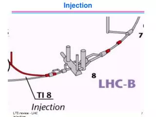
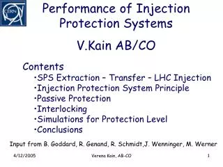
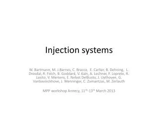
Injection systems W. Bartmann, M. J.Barnes, C. Bracco, E. Carlier, B. Dehning, L. Drosdal, R. Folch, B. Goddard, V. Kain, A. Lechner, F. Loprete, R. Losito, V. Mertens, E. Nebot DelBusto, J. Uythoven, G. Vanbavinckhove, J. Wenninger, C. Zamantzas, M. Zerlauth MPP workshop Annecy, 11th-13th March 2013
Outline • HW changes • AGK logic • Connections to injection BETS • TCDI settings and validation • Temporary inhibit of injection BLMs • Steering and IQC Injection, MPP workshop
MKI upgrades for LS1 (I) • Presently installed MKIs have 15 screen conductors - rather than a full complement of 24 • 24 conductors would not originally work for high voltage, breakdown reasons Beam screen upgrade 1mm gap between ceramic tube and conducting cylinder Screen conductors 3mm gap between ceramic tube and conducting cylinder Injection, MPP workshop
MKI upgrades for LS1 (II) • 24 screen conductors for all magnets • expected to reduce beam induced heating by a factor of approximately 3 to 4 • to achieve this several modifications are being made to the beam screen • remove some of the metallization, at the end of the ceramic tube, and replace it with a conducting tube which is spaced from the ceramic • preliminary test results indicate that this modification has increased the voltage at which surface flashover occurs by at least50% Injection, MPP workshop
MKI upgrades for LS1 (III) NEG coated bypass tubes • Copper bypass tubes will be NEG coated (suppress ecloud) • Increased emissivity of inside of MKI tank (improved cooling of ferrite yoke) • Vacuum system, in the MKI areas, to include: • for the CW transition: • NEG coating of the Cu Insert • Installation of new dome on both side of the sector valves with a D400 NEG cartridge • 2 x Ion pump • All the BTVSIs and BPTXs will be NEG coated. • The MKI Interconnects will be upgraded: • Exchange the ion pump to a version which also includes a NEG cartridge; • NEG coating of the Cu insert of the warm bellow module • Improved cleaning of ceramic tubes to reduce UFOs – already done on the MKI8d installed during TS3, results look promising Injection, MPP workshop
MKI ongoing studies • Cr2O3coating of the ceramic tube (and subsequent SEM analysis) to further increase flashover voltage and reduce SEY • Might put one coated ceramic tube in during LS1 to get experience, can be exchanged in case it doesn’t work • Surface flashover voltage as a function of pressure • Beam coupling impedance measurements and comparison with computer models A. Perez EN-MME Injection, MPP workshop
TDI upgrades during LS1 Temporarily reinforced screen • During LS1 the two TDIs in TI2 and TI8 will be removed and upgraded. The existing spare will be upgraded as well, and a second spare will be constructed. • Technical upgrades foreseen • Beam screen: • New reinforced stainless steel, copper coated beam screen, and new supporting frame • New sliding systems • Replacement of the central RF fingers by a mechanical connection • RF extremities bolted instead of EB welded • Addition of 16 temperature sensors • Replace the grease of the gearbox by a coating to avoid the risk of torque increase due to the radiation effects New beam screen (prototype) Injection, MPP workshop
Bolted connection for the central RF transition Bolted connection of the RF extremities Technical improvements of the beam screen of the TDI New design of the sliding system
TDI upgrade during LS1 • Launch of 2nd TDI spare – with lower priority • Discussions ongoing for the coatings with vacuum and impedance teams • If Ti can be taken out possibly thin layer of copper (1um) • On top NEG to reduce the SEY • Has to be verified that for grazing impact copper does not sublimate, FLUKA simulations ongoing Injection, MPP workshop
Abort gap keeper (AGK) • Connecting the AGK not only to the MKI but also the SPS extraction • impossible for timing because beam is not always at the same position in the SPS • Improve the AGK monitoring • Provide after each injection a measure of • the delay between the end of the AGK and the trigger of the MKI and • the delay between the trigger of the MKI and the beginning of the AGK • Sum of these 2 delays and the length of the AGK should be 1 turn Injection, MPP workshop
Connections to injection BETS • Connecting MSI current is foreseen • Connecting the TDI gap • Issue is that wrong TDI settings must not inhibit the MKI pulse but the SPS extraction • Something similar already in place for MKI erraticswhich can inhibit ~90 % of the cases where beam is dumped on the TDI due to erraticsduring the PFN charge up • Extract signal from INJ_BETS and connect to maskable BIS input, this allows to move the TDI while setup • Need to rely on position monitoring of the TDI • In discussion phase, will be followed up after the WS Injection, MPP workshop
TCDI settings and validation • TCDI settings were wrong in 2012 after optics change • Use concept of SIS beta* check as for LHC ring • Define virtual beta* for TL optics and use the SIS-SMP-MTG chain as for gap control of TCTs • For each TL optics store quad currents and associate unique virtual beta* • SIS reads reference settings, compares to published extraction currents for every cycle and if within tolerance publish value, if not publish 0 • From TCDI side read beta* value and check if within limits Injection, MPP workshop
TCDI settings and validation • TCDI settings, beta* values and optics are stored in a single BP, if the BP is wrong SIS check will fail • To be added to existing infrastructure • Reference settings for TL quads + virtual beta* • Beta* limits for TCDIs • Need to implement interlocking on beta* for TCDI front-ends • New SIS code Injection, MPP workshop
Temporary inhibit of injection BLMs • BLM team has a big monitor re-grouping campaign in LS1 • From C. Zamantzas’ MPP presentation on 30-Nov-11 option 2 to be adapted: • Create two crates (P2 and P8) dedicated to sunglass BLMs • Use LICs to be put in dedicated crates • Start machine in this configuration • If necessary, modify cards and go for the blinding on external trigger • Progress • Test LICs in lab - done • Install a subset in the machine to test their performance- done • Group them in dedicated crates – in LS1 • Modify the cards to allow triggering on an external signal – during operation after LS1; requires approval by (r)MPP • Monitor list provided by ABT • In case the inhibit is added to a crate, ALL monitors of this crate are blinded, take into account redundancy when adding monitors to the list , eg mix LICs without inhibit and standard ICs with inhibit Injection, MPP workshop
BLM list B1 Injection, MPP workshop
BLM list B2 Injection, MPP workshop
Operational • Steering • Work ongoing to improve stability of SPS MSE power converters • 6 or 12 bunches to be placed on MKE waveform such as to be representative for the full batch (during setup) • In case of using the full batch for correction calculation OR LHC orbit correction always come back to intermediate intensity for the next injection • IQC • IQC will have to become partly safety critical not only quality check • Resetting of injection oscillation only once per filling - enforced by software? • In case of reset check with explicit comment by EIC • Two levels of IQC BLM thresholds, warning at ~10%, block at 50% of dump threshold Injection, MPP workshop
Summary (I) • Ugrades of MKI aimed at reducing HV breakdowns of screen, impedance, ecloudand UFO rate and at improved cooling • Both TDIs will be taken out and upgraded • also the spare to be upgradedand another spare to be constructed (maybe not ready for startup) • More robust screen and improved sliding system • Replacement of RF fingers and additional temperature sensors • Coating under discussion • AGK • Connection to SPS extraction not possible • Improve monitoring of AGK delays wrt MKI trigger Injection, MPP workshop
Summary (II) • Injection BETS • Connect MSI current and TDI gap • In case of wrong TDI gap MKI must not be inhibited but SPS extraction • Connect INJBETS to maskable BIS input to allow for TDI setup • TCDI settings and validation • Use virtual beta* and SIS check for TCDI gap validation • Temporary inhibit of injection BLMs • 1 crate per P2 and P8 will be available for sunglass BLMs • LICs are tested and found OK for installation in LS1 • Modification of cards to allow triggering on external signal foreseen during short stop in operation if necessary • IQC to become partly safety critical • Only one reset of injection oscillations per fill? • Reset with EIC comment • Increased loss levels with blocking above 50% dump threshold Injection, MPP workshop