Download
1 / 19
190 likes | 434 Vues
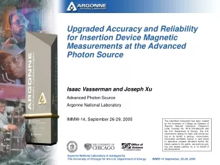
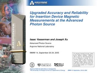
Upgraded Accuracy and Reliability for Insertion Device Magnetic Measurements at the Advanced Photon Source. Isaac Vasserman and Joseph Xu Advanced Photon Source Argonne National Laboratory IMMW-14, September 26-29, 2005.

E N D
Upgraded Accuracy and Reliability for Insertion Device Magnetic Measurements at the Advanced Photon Source Isaac Vasserman and Joseph Xu Advanced Photon Source Argonne National Laboratory IMMW-14, September 26-29, 2005 The submitted manuscript has been created by the University of Chicago as Operator of Argonne National Laboratory (“Argonne”) under Contract No. W-31-109-ENG-38 with the U.S. Department of Energy. The U.S. Government retains for itself, and others act-ing on its behalf, a paid-up, nonexclusive, irrevocable worldwide license in said article to reproduce, prepare derivative works, dis-tribute copies to the public, and perform pub-licly and display publicly, by or on behalf of the Government.
Outline • Main components of the system • Architecture • Specifics of new coil and Hall probe systems • Definitions and formulas for calculations • Main parameters • Accuracy and reproducibility • Conclusion
Introduction • The previous upgrade to the APS magnetic measurement system [1], in 2002-2003, focused on selecting the best measurement techniques and analysis algorithms. It was reported at IMMW 13 [2]. • The most recent upgrade focused on improving reliability and reproducibility based on the FPGA technology [3,4]: • Hardware acknowledgment protocol between the quadrature encoder readout and the DMM provides reliable one-to-one synchronization between signal measurement and sensor position • Absolute position readout at the speed of 40 MHz produces consistent high precision measurement results at a higher scanning speed • Coil angular position with a time stamp of up to 120 MHz clock yields high precision digital signal integration • Results: • 10-fold improvement in reproducibility of rotating coil field integrals, to ~0.1 G-cm for 1st integral and 20 G-cm2 for 2nd • 5-fold improvement in reproducibility of Hall probe measurements • Easy switching between stretched rotating coil and single stretched wire measurements because both are mounted
Measurement Sensors List • Hall probe: 2-axis Hall probe (Sentron type) • Moving coil Short (3 undulator period or less) coil instead of Hall probe • Stretched rotation coil: 10-turn Litz wire coil; width of the coil is 5 mm • Single stretched wire: 10-turn Litz wire coil with one side kept stable and the other side moving in the X-direction
6-m Bench Magnetic Measurement System Stretched wire is stretched by weight, so the tension is independent of the distance between the supports. Rotating coil tension is regulated by springs and depends on the distance between the supports. Stretched wire Rotating coil Hall probe
Coil Control and DAQ System Architecture System control and data acquisition architecture schematic layout for integrated coil system. Hall probe system includes additional DMM board.
APS Magnetic Measurement System • Stretched coil • Rotating mode • First field integrals (horizontal and vertical) measurements • Second field integrals (horizontal and vertical) measurements • Multipole components of first field integral measurements • Translation mode • Multipole components of first field integral measurements • Single stretched wire • First field integrals (horizontal and vertical) measurements • Second field integrals (horizontal and vertical) measurements • Hall probe • Field map, phase errors, field integrals • Movingcoil • Reference for field integrals
Some Examples of the Control Screens Rotating coil multipole scan Main control screen Single stretched-wire scan 1st field integral scan by rotating coil 2nd field integral scan by rotating coil Stretched coil horizontal field scan for multipoles
Magnetic flux of rotating coil with N turns: where Jy,x are components of the first field integrals, d is the coil width. This expression is valid, when the field integral change over the width of the coil (5 mm in our case) is small enough to allow fitting to the sinusoidal function. First field integrals could be found by integrating the signal and fitting the dependence of flux on time.
Second Field Integrals of the Coil Rotating Mode • One end of the coil is rotated by 180 (figure 8 coil) [5]. The measurement consists of then rotating the entire coil, while retaining the figure 8 twist. Here Φx,y are a and b terms from the equations on the previous slide, L is the length of the coil, θ=2d/L (+ or – is determined by the direction of the twist) • The stretched wire case is similar to the above except the two ends of the wire are translated in opposite direction [3]
Coil Translation Mode • In translation mode, the coil moves in the X direction and the difference in flux from initial value is measured. • The plane of the coil is oriented vertically to measure the horizontal component of the field integral, and horizontally to measure the vertical component. • This option is preferable for multipole component measurements. The main source of distortions (wire vibration) is less than that of the single wire in this case.
Parameters of the Coil System • The angular encoder is multiturn with 0.005 degree resolution. • The linear encoder has 0.5 micron resolution and measures the linear position of the coil or single wire. • A differential DC signal amplifier with low-pass signal filter and auto zero suppression is used. The signal conditioner pre-amplifies the coil signal ~3,000 times. The amplified signal is then fed to the 16-bit digitizer of an FPGA card. • The FPGA reconfigurable data acquisition card has eight 16-bit resolution analog inputs, 96 digital inputs/outputs, 25-ns time resolution, and 80 kB of onboard memory. The digital I/Os are programmed to read the encoder positions. • The analog inputs are configured to measure the coil signals synchronized with the position readouts and the time durations.
Latest Improvements in the Coil Measurements • Rotary encoder for rotating coil is used for synchronization • Precise synchronization of coil measurements with small steps and many data points, allowing for numerical integration with high precision • Reproducibility of a single measurement is exellent (≈ 0.1 G-cm of 1st field integral for 4 m long coil), so there is no need for averaging multiple scans; two scans usually are done just in case
New Hall Probe Control and DAQ System Specifics • Real-time measurements. • Unlimited number of points. • Field measurements with synchronous absolute position encoder readings. • Missing or duplicated points, if any, do not affect accuracy of measurements. Previously even one missing point created a problem because the location of the missing point was not known. • Reproducibility characterized by RMS point-by-point difference between two consecutive scans is ≈ 0.6 G for 2.4-m-long device with 0.8-T peak field. • 20-bit resolution DMM card is used for Hall probe measurements.
New Hall Probe (cont.) • The next slide shows the results of scans with the old and new Hall probe measurement systems. The difference between the two consecutive scans is plotted. • The same performance could be achieved with a slow scan speed and large integration time, or with a high scan speed, small integration time, and larger number of points, separated by smaller steps. High speed is preferable, because the scan finishes sooner and the higher resolution in the field map is especially important for short ID periods. The new system does not have a limitation on points numbers and allows a smaller step size and more points, so this option can be used without decreasing the performance.
Two Scan Subtraction New system. Speed 75 mm/s, RMS=1.1 G, T=1 ms (top) Old system. Speed 75 mm/s, RMS=4.6 G (bottom)
Field Difference of Two Scans The main contribution to the difference is due to the probe carriage mechanical jitter and, as expected, comes from near the zero crossings, where the slope is highest.
Conclusions • The new magnetic measurement system uses the same architecture of control (hardware and software) for each type of measurement. • Very good reproducibility makes it unnecessary to average many scans. Data collection is much faster. • Real-time system with small steps and large number of points allows for precise control of position and triggering time of measurements. Integrations are done numerically, thereby eliminating problems associated with zero drift of integrators (flux meters). • All components of the magnetic measurement system (including video cameras) are available online, and measurements could be done from any location with an Internet connection.
References • Y. Eidelman, B. Deriy, O. Makarov, I. Vasserman, “The New Magnetic Measurement System at the Advanced Photon Source,” ICALEPCS 2001, November 2001, 160-163, TUAP051. • I. Vasserman, “APS Magnetic Measurement Facility. Comparison of Different Magnetic Measurement Techniques,” 13th International Magnetic Measurement Workshop, May 2003, Stanford, CA. • J. Z. Xu, private communication. • Joseph Z. Xu, Isaac Vasserman, “A New Magnetic Field Integral Measurement System,” PAC 2005, Knoxville, Tennessee, May 16-20, 2005, to be published. • D. Frachon, I. Vasserman, P.M. Ivanov, E.A. Medvedko, E. Gluskin, and N. A. Vinokurov, “Magnetic Measurements of the Elliptical Multipole Wiggler Prototype,” IMMW-9, June 1995, Saclay, France, ANL/APS/TB-22, March 1995.