Download
1 / 10
100 likes | 410 Vues
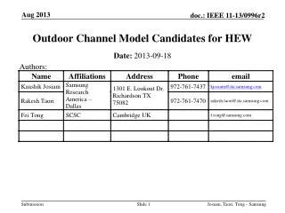
Outdoor Channel Models for 802.11ah. Authors:. Date: 2011-02-18. Slide 1. Summary. 802.11ah targets several outdoor applications with increased range up to 1km and in S1G frequencies

E N D
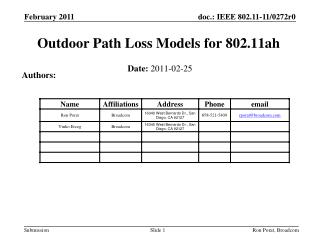
Outdoor Channel Models for 802.11ah Authors: Date: 2011-02-18 Ron Porat, Broadcom Slide 1
Summary • 802.11ah targets several outdoor applications with increased range up to 1km and in S1G frequencies • Cellular systems have been successfully deployed in similar frequencies (2G/3G 800-900MHz), LTE in the US in 700MHz • We look at channel models used for 3GPP LTE system performance assessment and provide a summary • Channel models include a spatial component (for MIMO performance assessment), path loss and delay spread • Provided as well are some results from measurement campaigns in 700 and 900MHz and from deployed 3G systems. Ron Porat, Broadcom Slide 2
3GPP System Simulation Parameters • Based on [1] the following simulation scenarios were defined for the development of LTE release 8. Note that: • Simulation case 4 uses 900MHz • Penetration loss of 10dB is assumed for 900MHz • Micro cell assumptions may be suitable to hotzone deployment Table A.2.1.1-2 EUTRA micro-cell simulation cases for MIMO * Penetration loss is included in the distance dependent pathloss model Ron Porat, Broadcom Slide 3
Cont. – Macro Cell Parameters Table A.2.1.1-3 – Macro-cell system simulation baseline parameters Ron Porat, Broadcom Slide 4
Path Loss Models • Models are based on [5], [6] • Macro cell propagation model for urban area is applicable for scenarios in urban and suburban areas outside the high rise core where the buildings are of nearly uniform height • h is the antenna height above roof top levels and assumed 15m • R is in [km] and f in [MHz] • Macro cell propagation for the rural area can be found in [6] • Ref [7] by NIST makes use of these models to analyze the coverage and throughput of LTE deployed for smart grid • Ref [2] (section A.2.1.1.2) discusses newer deployments as per rel. 10 of LTE whereby pico cells, remote radio heads, and relays are considered. Some more path loss models are described therein. Ron Porat, Broadcom Slide 5
Spatial Channel Model • Adopted by 3GPP and 3GPP2 as the model to assess MIMO channel performance. • Fully described in [3] and freeware Matlab implementation can be downloaded from [4]. • Channel realizations are generated through the application of the geometrical principle by summing contributions of rays (plane waves) with specific small-scale parameters like delay, power, angle-of-arrival (AoA) and angle-of-departure (AoD). Superposition results in correlation between antenna elements and temporal fading with geometry dependent Doppler spectrum. • RMS delay spread of 0.65uS/0.25/0.17uS for urban macro/micro and suburban deployments Ron Porat, Broadcom Slide 6
More on Outdoor Delay Spread • Ref [8] discusses measurements of 3G deployments in European cities and concludes that the rms delay spread is quite short (0.2uS) and close to 3GPP rural area delay spread profile as described in ref [9] • Ref [11] conducted delay spread measurements in the 900MHz band and the results show up to 2uS maximum delay spread. • Ref [12], [13] performed channel measurements in the 700MHz band in Colorado and Boulder. Results show delay spread below 2uS. • Ref [14] reports median rms delay spread values at 1km of 0.4-1us for urban macro cells. Ron Porat, Broadcom Slide 7
Conclusions • We recommend usage of 3GPP SCM and LTE path loss formulas for assessing link budget and MIMO system performance of outdoor 802.11ah deployments • The SCM channel model is very flexible and can be used for different environments by changing its parameters • The channel rms delay spread observed for macro cells is up to1uS • About 5-6 times that for total delay spread • Decisions on delay spread only require rough idea for proper design. For example: • At 5MHz BW and using FFT=256/128, a CP length of 1/8 provides 6.4/3.2uS of channel protection • Single parameter change, in this case FFT size, changes delay spread tolerance significantly (factor of 2) Ron Porat, Broadcom Slide 8
References [1] 3GPP TR 25.814 - Physical layer aspects for evolved Universal Terrestrial Radio Access (UTRA) – Annex A.2 system simulation scenario [2] 3GPP TR 36.814 - Further advancements for E-UTRA physical layer aspects, Annex A – simulation models. Annex B- channel models [3] 3GPP TR 25.996 - Technical Specification Group Radio Access Network; Spatial channel model for Multiple Input Multiple Output (MIMO) simulations [4] Link to Matlab implementation of [3] http://radio.tkk.fi/en/research/rf_applications_in_mobile_communication/radio_channel/scm-05-07-2006.zip [5] 3GPP TR 25.942 - Radio Frequency (RF) system scenarios - sections 5.1.4.2/5.1.4.3 – Macro/Micro propagation model [6] 3GPP TR 36.942 - Radio Frequency (RF) system scenarios –sections 4.5.2/4.5.3 Macro cell propagation model [7] LTE Smart grid Analysis - http://collaborate.nist.gov/twiki-sggrid/pub/SmartGrid/PAP02Wireless/LTE_SmartGrid_Analysis.ppt [8] How typical is the "Typical Urban" channel model? Ericsson Research [9] 3GPP 25.943 – Description of channel models Ron Porat, Broadcom Slide 9
Cont. [10] Impulse Response Measurements in the 902-928 and1850-1990 MHz Bands in Macrocellular Environments – NTIA and Bell Atlantic Mobile, 1993 [11] 15-09-0279-01-004g-channel-characterization-for-sun.ppt [12] 700 MHz Band Channel Propagation Model http://www.nist.gov/itl/antd/emntg/700mhz.cfm [13] A Channel Propagation Model for the 700 MHz Band – NIST and Sandia National Labs ICC 2010 [14] A New Path-Gain/Delay-Spread Propagation Model for Digital Cellular Channels, Larry J. Greenstein, Vinko Erceg, Yu ShuanYeh, and Martin V. Clark, Ron Porat, Broadcom Slide 10