TEAM LLAMP
The project aims to develop an innovative multi-touch LED lattice using advanced design techniques within the Department of Electrical and Computer Engineering. This documentation includes a critical design review outlining the frame fabrication, assembly parts list, updated timeline, division of labor, and expected deliverables. It details the approach for touch input processing, including PCB layouts and UIA bus definitions, alongside test results and system performance evaluations, ensuring effective collaboration among team members, including Nadja Memic, Steve Karcher, Sri Teja Basava, and Francis Yi.

TEAM LLAMP
E N D
Presentation Transcript
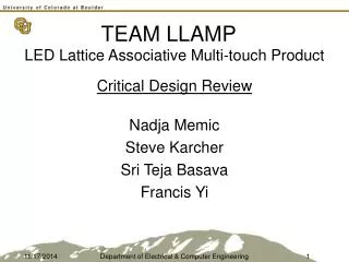
TEAM LLAMP LED Lattice Associative Multi-touch Product Critical Design Review Nadja Memic Steve Karcher Sri Teja Basava Francis Yi Department of Electrical & Computer Engineering
CDR Outline • Frame Fabrication • IPB Subassembly • Parts List • Revised Timeline • Updated Division of Labor • Milestone/Expo Deliverables • Questions? • System Drawing • Outline of Approach • Frame • Tx & Rx Subassembly • PCB Layout • UIA Bus Definition • Demo & Test Results Department of Electrical & Computer Engineering
System Drawing Department of Electrical & Computer Engineering
Outline of Approach Touch Input FPGA w/ Supporting Hardware Frame Input Processing Box 5 3 5 8 Control Signals & Data Ribbon Cable Serial Mouse Coordinates Computer Driver Software Application (Drawing Tool) Mouse Coordinates Screen Output Department of Electrical & Computer Engineering
Frame 5 Tx Board Select Selected Tx On Tx Select 3 Rx Selected Rx Status 5 8 Board Select Department of Electrical & Computer Engineering
Tx Subassembly Department of Electrical & Computer Engineering
Frame 5 Tx Board Select Selected Tx On Tx Select 3 Rx Selected Rx Status 5 8 Board Select Department of Electrical & Computer Engineering
Rx Subassembly Department of Electrical & Computer Engineering
PCB Layout Revision 1 Department of Electrical & Computer Engineering
Pin Name Description Default Level 1 VDD6 +6V DC supply for logic chip +6V DC 2 VDD18 +18V DC supply as noise contingency +18V DC 3 GND0 System ground 0V DC 4 GND1 System ground 0V DC 5 TX7 Board ID 5 [●○○○ ○---] CMOS LOW 6 TX6 Board ID 4 [○●○○ ○---] CMOS LOW 7 TX5 Board ID 3 [○○●○ ○---] CMOS LOW 8 TX4 Board ID 2 [○○○● ○---] CMOS LOW 9 TX3 Board ID 1 [○○○○ ●---] CMOS LOW 10 TX2 Transmitter ID 3 [---- -●○○] CMOS LOW 11 TX1 Transmitter ID 2 [---- -○●○] CMOS LOW 12 TX0 Transmitter ID 1 [---- -○○●] CMOS LOW 13 RX4 Board ID 5 [●○○○○] CMOS LOW 14 RX3 Board ID 4 [○●○○○] CMOS LOW 15 RX2 Board ID 3 [○○●○○] CMOS LOW 16 RX1 Board ID 2 [○○○●○] CMOS LOW 17 RX0 Board ID 1 [○○○○●] CMOS LOW 18 D7 Data transmit bit 8 [●○○○ ○○○○] CMOS LOW 19 D6 Data transmit bit 7 [○●○○ ○○○○] CMOS LOW 20 D5 Data transmit bit 6 [○○●○ ○○○○] CMOS LOW 21 D4 Data transmit bit 5 [○○○● ○○○○] CMOS LOW 22 D3 Data transmit bit 4 [○○○○ ●○○○] CMOS LOW 23 D2 Data transmit bit 3 [○○○○ ○●○○] CMOS LOW 24 D1 Data transmit bit 2 [○○○○ ○○●○] CMOS LOW 25 D0 Data transmit bit 1 [○○○○ ○○○●] CMOS LOW 26 GND2 System ground 0V DC UIA Bus Definition Revision 1 Department of Electrical & Computer Engineering
PCB Revision 1 Original board select algorithm – decode address on each board 3500mil x 3400mil = 11.9 inches2 10 Address bits 3 Tx ID bits 8 Data bits 10 DIPs Fewer wires, generic solution Department of Electrical & Computer Engineering
PCB Layout Revision 2 Department of Electrical & Computer Engineering
Pin Name Description Default Level 1 VCC Positive power supply +6V DC 2 GND System Ground 0V DC 3 Ena01 Enable Board 1 CMOS LOW 4 Ena02 Enable Board 2 CMOS LOW 5 Ena03 Enable Board 3 CMOS LOW 6 Ena04 Enable Board 4 CMOS LOW 7 Ena05 Enable Board 5 CMOS LOW 8 Ena06 Enable Board 6 CMOS LOW 9 Ena07 Enable Board 7 CMOS LOW 10 Ena08 Enable Board 8 CMOS LOW 11 Ena09 Enable Board 9 CMOS LOW 12 Ena10 Enable Board 10 CMOS LOW 13 Ena11 Enable Board 11 CMOS LOW 14 Ena12 Enable Board 12 CMOS LOW 15 Ena13 Enable Board 13 CMOS LOW 16 Ena14 Enable Board 14 CMOS LOW 17 TxID1 Transmitter ID 1 MSB[○○●]LSB CMOS LOW 18 TxID2 Transmitter ID 2 MSB[○●○]LSB CMOS LOW 19 TxID3 Transmitter ID 3 MSB[●○○]LSB CMOS LOW 20 Cntrl Behavior Identifier Tx LOW Rx HI 21 Data1 Data bit 1 MSB[○○○○ ○○○●]LSB CMOS LOW 22 Data2 Data bit 2 MSB[○○○○ ○○●○]LSB CMOS LOW 23 Data3 Data bit 3 MSB[○○○○ ○●○○]LSB CMOS LOW 24 Data4 Data bit 4 MSB[○○○○ ●○○○]LSB CMOS LOW 25 Data5 Data bit 5 MSB[○○○● ○○○○]LSB CMOS LOW 26 Data6 Data bit 6 MSB[○○●○ ○○○○]LSB CMOS LOW 27 Data7 Data bit 7 MSB[○●○○ ○○○○]LSB CMOS LOW 28 Data8 Data bit 8 MSB[●○○○ ○○○○]LSB CMOS LOW 29 NC1 Reserved for future use NC 30 NC2 Reserved for future use NC UIA Bus Definition Revision 2 Department of Electrical & Computer Engineering
PCB Revision 2 Revised board select algorithm – one enable line per board 2000mil x 3850mil = 7.7inches2 1 Enable/board – 14 total 3 Tx ID bits 8 Data 5 SOIC, SOT353 Fewer parts, no loading, less expensive Department of Electrical & Computer Engineering
Demo Department of Electrical & Computer Engineering
Demo Department of Electrical & Computer Engineering
Test Results Digital signals D[15:11] measure the board select, while the transmitter ID is on D[10:8]. The trigger fires when the board is manually selected (changed from 01000 to 01010), and the delay time between board select and transmitter response is measured to be 788 ns. Department of Electrical & Computer Engineering
Test Results Digital signals D[15:11] measure the board select, while the transmitter ID is on D[10:8]. The trigger fires when the board is manually de-selected (changed from 01010 to 00010), and the delay time between board de-select and transmitter response is measured to be 1046 ns. Department of Electrical & Computer Engineering
Test Results Digital signal D3 triggers when the board is selected. Between the trigger and D7, the measured response time is 191 ns. This is the response of the receive circuit independent of the transmit circuit. Department of Electrical & Computer Engineering
Test Results D[2:0] are the transmitter select signals. When transmitter 000 is selected, we observe the voltage driving the transmitter (violet) and the voltage indication on the photo-transistor (yellow). The digital signal representing the response is measured on D7 to be 2121 ns from the stimulus. Department of Electrical & Computer Engineering
Frame Fabrication • Dimensions: Front/Back Image Department of Electrical & Computer Engineering
Frame Fabrication • Dimensions: Side Image Department of Electrical & Computer Engineering
Frame Fabrication Department of Electrical & Computer Engineering
Frame Fabrication Department of Electrical & Computer Engineering
Frame Fabrication Department of Electrical & Computer Engineering
Frame Fabrication Department of Electrical & Computer Engineering
Frame Fabrication Department of Electrical & Computer Engineering
IPB Subassembly Department of Electrical & Computer Engineering
Transmitting Part 1… Department of Electrical & Computer Engineering
Are any data bits set? Reading Part 1… Department of Electrical & Computer Engineering
Isolating… Department of Electrical & Computer Engineering
Parts List Department of Electrical & Computer Engineering
Revised Timeline Department of Electrical & Computer Engineering
Updated Division of Labor and Responsibilities • 1.Frame: • - Fabrication • - PCB/Soldering • - Assembly • 2.Input Processing Box: • - Loading Nios II onto FPGA • - Logic algorithm development • - Creating a board for FPGA • 3.Driver Development: • - Updating, averaging, proximity & toggling • Software Application: • - Implementation of painting ftn Nadja & Francis Entire Team Steve, Teja, & Nadja Steve, Teja, & Francis Francis & Teja Nadja & Steve Steve & Nadja Teja & Francis Department of Electrical & Computer Engineering
Milestone 1 (Nov 1) PCB complete Pick and place both revisions Test both revisions for speed and robustness Order board set and driver circuitry Boards mounted Machine acrylic Countersink mounting hardware Mount PCBs to UIA Cabling and set IDs Measure and place cable taps Set board IDs Test for uniqueness with a FPGA routine Milestone 2 (Nov 29) Cyclone support Develop support circuitry Layout PCB IPB Algorithms Develop Implement in C and logic gates RS-232 Interface Research Interface with NIOS II Testing and Debugging Open-Lab Expo (Dec 13) Application Develop front and back end Quality Assurance Milestone/Expo Deliverables Department of Electrical & Computer Engineering
Questions? Thank You! ? Department of Electrical & Computer Engineering
![[Team name] Team Award](https://cdn4.slideserve.com/678300/slide1-dt.jpg)