Download

1 / 9
170 likes | 644 Vues
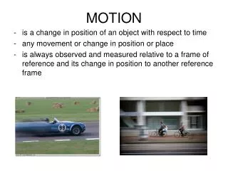
Allegro’s ATS642 Hall Effect Sensor “A great way to measure the speed and position of a rotating object” Michael Doogue Director of Strategic Marketing Allegro MicroSystems in Manchester, NH. What is a Hall Effect Sensor?.

E N D
Allegro’s ATS642 Hall Effect Sensor “A great way to measure the speed and position of a rotating object”Michael DoogueDirector of Strategic Marketing Allegro MicroSystems in Manchester, NH
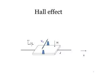
What is a Hall Effect Sensor? • Hall effect sensors are silicon chips that convert magnetic fields into electrical voltages • These sensors can be used to detect the proximity of a magnet or a ferromagnetic object • A ferromagnetic object is anything that a magnet will stick to! • The Hall effect sensor provided to the FIRST teams is a special type of Hall effect sensor • The sensor is used in anti-lock brake systems in automobiles to sense the speed, position and/or direction of a rotating gear • Sensor output is a digital signal that is representative of the profile of the object passing in front of the sensor • You can do a lot with this little sensor! Hall Sensor
Automotive Applications for Allegro Hall SensorsI told you that you could do a lot with Hall sensors! Convenience Systems Door lock Position Sensing Window Position/Speed Sensing Window/Sunroof Direction Sensing for anti-pinch Seating Systems Various Contactless Switches Motor Controllers/Drivers Wiper Systems LCD screens Electronic Power Steering Position Sensing Motor Commutation Current Sensing Powertrain Applications Cam/Crank Sensors Transmission Speed Sensors Throttle Position Sensors EGR Valve Position Sensors Valve Position Sensors Current Sensing Suspension Systems Position Sensing Chassis height Safety Systems Airbag Diagnostics & Control Occupant Sensing ABS/Traction - Wheel Speed Sensing
Element Hall IC MAGNET MAGNET ATS642: A Sensor and Magnet in a Single Package Grey denotes any material that a magnet will stick to High B Low B
Getting Started: What is this thing? 16 mA Quick review so that you understand what you are dealing with when using this sensor! 8 mA
ATS642: What Might You Do With It? • The device is an edge detector – the output is not analog • If you have a rotating shaft on a motor: • If you use a gear with teeth in front of the sensor then the sensor can also be used as a positional encoder that tells you when the shaft has rotated by a certain number of degrees • The number of degrees between sensor output transitions depends on gear geometry and number of teeth on the gear • Can also be used to measure the distance of travel for a wheel by counting the number of digital transitions for a uniform gear • Motor rotation speed information can be detected by measuring the time between output edges with a microprocessor or timer circuit • Summary of applications: • Motor shaft or wheel speed/velocity measurement • Motor shaft or wheel distance measurement via counting of edges. Gear at right has 60 teeth so 60 rising edge output transitions means that the gear has rotated one full revolution • Can also use a “single tooth” ( maybe a screw) and obtain one output pulse per revolution • Advanced users: direction of rotation sensing • Must use a gear with wide teeth and narrow valleys or vice versa • Requires precise timer circuit to detect duty cycle of output signal • Duty cycle is ratio of t1 and t2 t1 t2
Getting Started: Applications Circuit • There is a power pin and a ground pin for this electronic device, but no output pin • The digital output is actually the electrical current consumed by the device: 8 mA or 16 mA flowing into Vcc pin and out of GND pin • A sense resistor and either an amplifier (comparator) or microprocessor can be used to measure the voltage across the sense resistor: for example VOUT(L) node at right • Consult your mentors (or me, via e-mail) regarding comparator circuits that can be used to convert the current output of the ATS642 into a voltage (I am not sure what you guys have in your device kits) • You may also use a low side resistor and a single microprocessor input to process the signal • The voltage across the sense resistor is proportional to the current passing through the resistor (ohms law) Voltage drop across resistor = 16 mA * RSENSE • Be careful that the voltage drop across the device sense resistor does not reduce the voltage across the sensor to a level < 4 V across the sensor leads (or else the device will not operate)
DOs and DON’Ts When Using This Sensor • Be certain that the branded face of the sensor faces the object to be sensed • Decrease the gap between the sensor face and the object to be sensed as much as possible • Make sure that a magnet (like the one in the 642!) will stick to the object to be sensed • Use deep valleys between any teeth that you are trying to sense on a gear (shoot for at least 5 mm tall teeth) • Align the sensor as shown in this drawing • Feel free to e-mail me with questions at doogue@alum.dartmouth.org • Look at the ATS642 datasheet at http://www.allegromicro.com/datafile/0642.pdf • Place the sensor more than 3 mm away from the object to be sensed (if possible) • Allow the voltage across the sensor leads to fall below 4 V (be careful to size your sense resistor appropriately) • Surround the sensor with ferromagnetic material that is closer to the sensor than the object to be sensed • Rotate the device 90 degrees with respect to this drawing. If the leads of the device are in the same plane of a gear then the device will not work!
Good luck and Thank You for Your TimeCome see me after this talk for a demo of a Hall sensor at work!Michael DoogueDirector of Strategic MarketingAllegro MicroSystems, Inc.Manchester, NHdoogue@alum.dartmouth.org