Download
1 / 45
460 likes | 601 Vues
RECENT RESEARCH TO BETTER UNDERSTAND WHEEL RIM AXIAL RESIDUAL STRESS AND VERTICAL SPLIT RIM WHEEL FAILURES November, 2012. bringing heavy haul freight rail transportation to the World. Presentation Outline. Vertical Split Rim (VSR) Wheel Failures Background Information The VSR Puzzle

E N D
RECENT RESEARCH TO BETTER UNDERSTAND WHEEL RIM AXIAL RESIDUAL STRESS AND VERTICAL SPLIT RIM WHEEL FAILURES • November, 2012 bringing heavy haul freight rail transportation to the World
Presentation Outline • Vertical Split Rim (VSR) Wheel Failures • Background Information • The VSR Puzzle • Drop Hammer Research Efforts • Residual Stress Measurements From the Tread Surface • Radial Slices – X-ray Diffraction • Axial Residual Stress – At & Away From Failure • Out-of-round and Axial Residual Stress • Wheel Truing and Axial Residual Stress Information presented in this document is considered confidential and should not be distributed without the expressed written consent of Amsted Rail Company Inc.
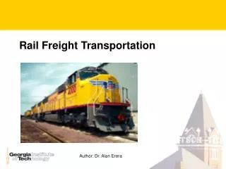
Vertical Split Rims • VSRs start almost exclusively at tread damage • Typically, a circumferential section of the front rim face breaks off, and wheel can drop into gage
Observations on VSRs by Dick, et al. on 68 wheels • VSRs length is typically 15 cm to entire circumference • Typically VSR is 25 to 70 mm from wheel’s front rim face • 263K GRL and 286K GRL cars have similar number of VSRs • Covered hoppers had most VSRs with 15/17 on B end • 62/68 wheels were 36” or 38”, only 6/68 were 33” • Not all were thin rimmed wheels • Most VSRs had hollow tread wear • VSRs more common in winter months • Most VSRs were impacting before failure • Both forged and cast wheels have VSRs
The VSR Puzzle • Historical VSR failure analysis did not identify conclusive root cause(s) • No material abnormalities • Hardness OK • Cleanliness normal • Microstructure/transformation - normal • No evidence of thermal overload • TTCI microcleanliness tests - 28/30 VSRs passed • Drop hammer, 30,000+ impacts – no failure
VSR Puzzle - UT and Chemistry • Griffin collects and records ultrasonic signal data for all wheels tested in plants after manufacturing. • Max UT signal data noted during testing was retrieved for 26 VSR wheels. • Distribution of signals for VSR wheels was the same as for 24,000 normal production wheels from 2006. • Also S and P values for a group of VSR wheels was less than the average S and P values for production wheels. • MnS inclusions directly related to Sulfur content.
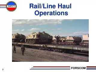
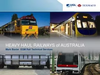
Drop Hammer Research Efforts • Tried to create a VSR in lab setting • Found tread damaged wheelsets that could be susceptible to impact damage • Used ASF-Keystone drop hammer, Camp Hill, PA, on wheel tread to simulate service impact load • Goal – Determine critical impact load and load location • Tread damaged wheel hit more than 31,000 times in a drop hammer with 250-300 kips impact load • Did not create VSR but wheel rim was severely deformed
ASF Keystone drop hammer can impart dynamic loads up to 2,000 kips – well in excess of 200 kips occasionally seen in service.
ASF-Keystone Drop Hammer was modified to accept a wheelsetfor impact testing
Drop Hammer & FEA Research • 54 miles of service given wheel circumference • Cracks noted below tread damage • FEA work with condemnable wheel rim thickness 7/8”, and 100 kip point load 1” from front rim face showed 28.5 ksi axial stress at tape line • Also the hoop stress at the front rim face to plate fillet was 28.8 ksi - this helps to explain why VSR’s propagate the way they do, especially under high impact loads
Residual Stress Measurements from the Wheel Tread Surface • Contacted Lambda Research in Cincinnati • Started with x-ray diffraction and core drilling from the tread surface • Axial residual stress measurements (not hoop, not radial) • Initial testing to see if there were differences between new and VSR wheels
Core drill from tread surface NEW WHEEL VSR WHEEL
Radial slices – X-ray diffraction • Core drill and x-ray diffraction from tread surface only provided residual stress measurements up to a depth of 1/3 inch • Needed to determine stresses at locations below tread surface in the wheel rim • Asked Lambda Research for assistance • Focus on axial residual stress measurements • Did we need to strain gauge wheel every time before cutting slices, or can relaxation effect be ignored? • Also used American Stress Technologies, Pittsburgh
Axial Residual Stress Data – Used Wheels We do not know wheel service and thermal history
Axial Residual Stress At and AwayFrom Failure Edge 1.5” Away from crack face Adjacent to crack face
Max Axial Tensile Stress Values For Slices Tested At and Away (1.5” from FRF)
Max Axial Compressive Stress Values For Slices Tested At and Away (1.5” from FRF)
TIR and Axial Residual Stress • Higher out-of-round wheels tested exhibited a greater average maximum compression value and greater average tension value than low out-of-round wheels. • The average values for maximum axial compression and tension of the high out of round slices is -298.5 MPa and +159.2 MPa, respectively. • The average values for maximum axial compression and tension of the low out-of-round slices is -202 MPa and +153.5 MPa, respectively.
Detailed Testing of CB38 Wheel • Used, D steel (not expected to be different than C for as-mfg axial residual stress), 0.050 in. difference in TIR between 2 points, looking for max compression and max tension… • 90 mm from BRF, high OOR point • -230 MPa and +199 MPa • 90 mm from BRF, low OOR point • -213 MPa and +154 MPa • 70 mm from BRF, high OOR point • -236 MPa and +180 MPa • 70 mm from BRF, low OOR point • -246 MPa and +142 MPa
Two Adjacent VSRs, Axial Residual Stress Measurement Pattern Tension measured at each point along this line
Radial Slice Cut at VSR Origin Tension measured at each point along this line
Proposed VSR Failure Mechanism From ASME RTDF 2011 • Tread damage occurs due to shelling (RCF/thermal-mechanical shelling) or spalling (wheel slides) • Cracks propagate under rolling and pounding loads • Highly compressive layer at tread surface must be balanced by tension deeper below the surface • When cracks propagate into this tension zone, cracks can rapidly change direction in service, making VSRs more likely • Class U wheels had the tension zone much deeper below the tread surface – this, and lower loads, meant that U wheels did not often suffer VSRs
Effects of Machining on Axial Residual Stress • Wheels are re-machined to remove tread damage • 6 wheelsets with tread damage selected at a RR wheel shop • 2 wheelsets likely would have been scrapped for thin rim – were machined anyway • What does truing do to the residual stress distribution?
Role of Wheel Truing on Axial Residual Stress in Used Wheels Machining appears to reduce compression and tension, “flattening out” stress pattern These 2 wheels were not fully “cleaned up”
Axial Residual Stress Work Continues • X-ray diffraction testing, 2 suppliers • 6 original machined wheels from CN • 12 additional machined wheels from CN • 12 machined wheels from BNSF • Out-of-round wheels, testing at high OOR and low OOR points around the wheel • FAST train test
BNSF Havelock Machining/Residual Stress Tests • Does wheel truing reduce axial residual stress pattern? • 6 tread damaged wheelsets selected, forged and cast • All machined to remove tread damage • Amount of metal removed recorded: 1 - 6/16, 2 - 8/16, • 3 - 6/16, 4 - 6/16, 5 - 6/16, 6 - 3/16 • Slices cut out at Anderson for axial residual stress testing using x-ray diffraction at AST, Pittsburgh • Other BNSF out-of-round wheels with impact history also to be tested.
Average Axial Stress Values - Machined • “VSR 1.5” average is made up of 26 data sets from 21 different wheels • “VSR 3” average is made up of 19 data sets from 14 wheels • “Used Class C” average is made up of 22 data sets from 13 wheels • “Machined 1.5” wheel average is made up of 28 data sets from 28 wheels • “Machined 3” wheel average is made up of 24 data sets from 24 wheels. Information presented in this document is considered confidential and should not be distributed without the expressed written consent of Amsted Rail Company Inc.
Wheel Truing Tests - Conclusions • Wheel truing not only corrects tread/tread profile and removes tread damage, it reduces the magnitude of sub-surface axial tensile stress • For VSR wheels, average axial tensile stress was around 25 ksi (172 MPa) on the 1.5” line of x-ray shots • Maximum axial residual tensile stress seen in machined wheels was about 120 MPa, or 17.4 ksi • Wheel truing reduces the chance for VSR…..A VSR needs: • Tread damage • Propagating cracks into the rim under service rolling and impact loads • An axial tensile stress of sufficient magnitude below the surface to get the crack to run….
Questions? Information presented in this document is considered confidential and should not be distributed without the expressed written consent of Amsted Rail Company Inc.