Download

1 / 71
980 likes | 1.63k Vues
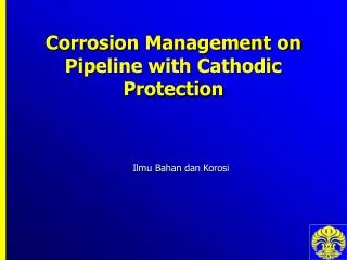
Cathodic Protection of Pipeline. Contents. CHAPTER ONE : principle of corrosion CHAPTER Two : Forms of corrosion CHAPTER THREE : Environment Effects CHAPTER FOURE : corrosion protection CHAPTER FIVE : preparation of pipeline

E N D
Contents • CHAPTER ONE :principle of corrosion • CHAPTER Two : Forms of corrosion • CHAPTER THREE:Environment Effects • CHAPTER FOURE : corrosion protection • CHAPTER FIVE : preparation of pipeline • CHAPTER SIX : Corrosion of pipeline • CHAPTER SEVEN :Cathodic protection of pipeline • CHAPTER EIGHT : Case Study
Ch.1 principles of corrosion • Introduction Corrosion is the destructive attack of a material by reaction with its environment. The serious consequences of the corrosion process have become a problem of worldwide significance. In addition to our everyday encounters with this form of degradation, corrosion causes plant shutdowns, waste of valuable resources, loss or contamination of product, reduction in efficiency, costly maintenance, and expensive over design; it also jeopardizes safety and inhibits technological progress. 1.1 corrosion definition • Corrosion is the deterioration of materials by chemical interaction with their environment. The term corrosion is sometimes also applied to the degradation of plastics, concrete and wood, but generally refers to metals. • Or Destruction of a metal by chemical or electrochemical reaction with its' environment. • Or A process in which a metal is destroyed by a chemical reaction
1.2 corrosion principles • The cathode is that portion of the metal surface where reduction takes place and does not dissolve. • The anode is that portion of the metal surface that is corroded. It is the point at which metal dissolves, or goes into solution. When metal dissolves, the metal atom loses electrons and is oxidised a. Corrosion occurs by an electrochemical process. The phenomenon is similar to that which takes place when a carbon-zinc “dry” cell generates a direct current. Basically, an anode (negative electrode), a cathode (positive electrode), an electrolyte (environment), and a circuit connecting the anode and the cathode are required for corrosion to occur (see Figure 1-1). Figure (1-1), dry cell
the predominant cathodic reaction is O2 + H2O + 4e- → 4(OH) eq (1-2 ) • The cathodic reaction that usually occurs in deaerated acids is 2H+ + 2e- → H2 eq (1-3) • In aerated acids, the cathodic reaction could be O2 + 4H+ + 4e- → 2H2O eq (1- 4) b. The number of electrons lost at the anode must equal the number of electrons gained at the cathode. • For example, if iron (Fe) was exposed to an aerated, corrosive water, the anodic reaction would be 2Fe → 2Fe ++ + 4e- (anodic) eq (1-5) O2 + 2H2O + 4e- → 4(OH- ) (cathodic)eq (1-6) • These can be summed to give the overall oxidation reduction reaction 2Fe + O2 + 2H2O → 2Fe ++ +4(OH- ) eq (1-7) c. After dissolution ferrous ions (Fe++) generally oxidize to ferric ions (Fe+++ ); these will combine with hydroxide ions (OH- ) formed at the cathode to give a corrosion product called rust (FeOOH or Fe2O3 x H2O).
1.3 classification of corrosion * General / Uniform Corrosion : • Atmospheric • Galvanic • Stray-current • General biological • High-temperature * Localized Corrosion • Filiform • Crevice • Pitting • Localized microbiological
Ch:2 Forms of corrosion 2.1 Uniform corrosion or general corrosion as sometimes called, is defined as a type of corrosion attack (deterioration) that is more or less uniformly distributed over the entire exposed surface of a metal (see illustration below). Fig (2-1) , uniform corrosion 2.1.1 Mechanisms The anodic reaction in the corrosion process is always the oxidation reaction: M = M+ + e- eq (2-1) In acidic environments, i.e., pH < 7, the cathodic process is mainly the reduction of hydrogen ions: 2H+ + 2e = H2 eq (2-2)
With uniform distribution of cathodic reactants over the entire exposed metal surface, reactions (2-2) take place in a "uniform" manner and there is no preferential site or location for cathodic or anodic reaction. The cathodes and anodes are located randomly and alternating with time. The end result is a more or less uniform loss of dimension. Fig (2-2) Real uniform corrosion • 2.1.2 Prevention or Remedial Action • Uniform corrosion or general corrosion can be prevented through a number of methods: • Use thicker materials for corrosion allowance • Use paints or metallic coatings such as plating, galvanizing or anodizing • Use Corrosion inhibitors or modifying the environment • Cathodic protection (SA/ICCP) and Anodic Protection • selection of a more corrosion resistant alloy (i.e. higher alloy content or more inert alloy) • utilize coatings to act as a barrier between metal and environment. • modify the environment or add chemical inhibitors to reduce corrosion rate See the details @www.metallurgy.eg.vg
2.2 Galvanic Accelerated corrosion which can occur when dissimilar metals are in electrical contact in the presence of an electrolyte (i.e. conductive solution). Fig (2-3) Galvanic corrosion 2.2.1 Mechanism Different metals and alloys have different electrochemical potentials (or corrosion potentials) in the same electrolyte. (i.e., the voltage) between two dissimilar metals is the driving force for the destructive attack on the active metal (anode). Current flows through the electrolyte to the more noble metal (cathode) and the less noble (anode) metal will corrode. Fig (2-4) Real example of Galvanic corrosion See the details @www.metallurgy.eg.vg
2.2.3 Prevention or Remedial Action • selection of alloys which are similar in electrochemical behavior and/or alloy content. • area ratio of more actively corroding material (anode) should be large relative to the more inert material(cathode). • use coatings to limit cathode area. • insulate dissimilar metals. • use of effective inhibitor. • Select metals/alloys as close together as possible in the galvanic series. • 2.3 crevice Crevice corrosion is a localized form of corrosion usually associated with a stagnant solution on the micro-environmental level This form of attack is generally associated with the presence of small volumes of stagnant solution in occluded interstices, beneath deposits and seals, or in crevices, e.g. at nuts and rivet heads. Deposits of sand,
Fig (2-5) Crevice corrosion 2.3.1 MECHANISM . Autocatalytic process are three stage : 2.3.1.1Stage one of a crevice formation ( Induction) Fig (2-6) Stage one of a crevice formation
2.3.1.2Stage two of a crevice formation (Restricted Convection) Fig (2-7) Stage two of a crevice formation (Restricted Convection) 2.3.1.3Stage three of a crevice formation(Obstruction and Electromigration) Fig (2-8)Stage three of a crevice formation(Obstruction and Electromigration)
2.3.2 Prevention • Crevice corrosion can be designed out of the system • Use welded butt joints instead of riveted or bolted joints in new equipment • Eliminate crevices in existing lap joints by continuous welding or soldering • Use solid, non-absorbent gaskets such as Teflon. • Use higher alloys for increased resistance to crevice corrosion • design installations to enable complete draining (no corners or stagnant zones) 2.4 Pitting Pitting: Pitting Corrosion is the localized corrosion of a metal surface confined to a point or small area, that takes the form of cavities. Pitting is one of the most damaging forms of corrosion Fig(2-9) Morphology of pitting
2.4.2 Mechanisms • For a homogeneous environment, pitting IS caused by the MATERIAL that may contain inclusions (MnS to pit initiation ) Fig (2-10) Real pitting corrosion • 2.4.3 Prevention or Remedial Action • * Pitting corrosion can be prevented through: • Proper selection of materials with known resistance to the service environment • Control pH, chloride concentration and temperature • Cathodic protection and/or Anodic Protection • increase velocity of media and/or remove deposits of solids from exposed metal surface See the details @www.metallurgy.eg.vg
2.5 Stress-corrosion cracking (SCC) • Stress-corrosion cracking (SCC) is a cracking process that requires the simultaneous action of a corrodent and sustained tensile stress. This excludes corrosion-reduced sections that fail by fast fracture. It also excludes intercrystalline or transcrystalline corrosion, which can disintegrate a alloy without applied or residual stress. Fig(2-11) stress corrosion cracking 2.5.1 Mechanisms Stress corrosion cracking results from the conjoint action of three components: (1) a susceptible material; (2) a specific chemical species (environment) and (3) tensile stress. See the details @www.metallurgy.eg.vg
2.5.2 Prevention • Stress corrosion cracking can be prevented through : • Control of stress level (residual or load) and hardness. • Avoid the chemical species that causes SCC. • Use of materials known not to crack in the specified environment. • Control temperature and or potential 2 .6 intergranular corrosion Intergranular corrosion is sometimes also called "intercrystalline corrosion" or "interdendritic corrosion". Fig (2-12) intergranular corrosion See the details @www.metallurgy.eg.vg
2.6.1 Mechanisms This type of attack results from local differences in composition, such as coring commonly encountered in alloy castings. Grain boundary precipitation, notably chromium carbides in stainless steels, is a well recognized and accepted mechanism of intergranular corrosion. The precipitation of chromium carbides consumed the alloying element - chromium from a narrow band along the grain boundary and this makes the zone anodic to the unaffected grains. The chromium depleted zone becomes the preferential path for corrosion attack or crack propagation if under tensile stress. Fig (2-13) intergranular corrosion • 2.6.2 Prevention • Intergranular corrosion can be prevented through: • Use low carbon (e.g. 304L, 316L) grade of stainless steels • Use stabilized grades alloyed with titanium (for example type 321) or niobium (for example type 347). Titanium and niobium are strong carbide- formers. They react with the carbon to form the corresponding carbides thereby preventing chromium depletion. • Use post-weld heat treatment.
2.7 selective leaching • *Dealloying is the selective corrosion of one or more components of a solid solution alloy. It is also called parting, selective leaching or selective attack. Common dealloying examples are decarburization, decobaltification , denickelification, dezincification, and graphitic corrosion or graphitization *Decarburization is the selective loss of carbon from the surface layer of a carbon-containing alloy due to reaction with one or more chemical substances in a medium that contacts the surface. *Dezincification is the selective leaching of zinc from zinc-containing alloys. Most commonly found in copper-zinc alloys containing less than 85% copper after extended service in water containing dissolved oxygen. Fig (2-14) forms of dezincification
2.7.1 Mechanisms Different metals and alloys have different electrochemical potentials (or corrosion potentials) in the same electrolyte. Modern alloys contain a number of different alloying elements that exhibit different corrosion potentials. The potential difference is the driving force for the preferential attack on the more "active" element in the alloy. Fig (2-15) dezincification • 2.7.2 Prevention • Dealloying, selective leaching and graphitic corrosion can be prevented through the following methods: • Select metals/alloys that are more resistant to dealloying. For example, inhibited brass is more resistant to dezincification that alpha brass, ductile iron is more resistant to graphitic corrosion than gray cast iron. • Control the environment to minimize the selective leaching
2 .8 Erosion Corrosion • Erosion corrosion is the corrosion of a metal which is caused or accelerated by the relative motion of the environment and the metal surface.as shown in Fig(2-16) Fig(2-16) Erosion corrosion 2.8.1 Mechanism There are several mechanisms described by the conjoint action of flow and corrosion that result in flow-influenced corrosion: * Mass transport-control: Mass transport-controlled corrosion implies that the rate of corrosion is dependent on the convective mass transfer processes at the metal/fluid interface. Fig (2-17) Real of erosion corrosion
*Erosion-corrosion: Erosion-corrosion is associated with a flow-induced mechanical removal of the protective surface film that results in a subsequent corrosion rate increase via either electrochemical or chemical processes. It is often accepted that a critical fluid velocity must be exceeded for a given material 2.8.2 Prevention or Remedial Action • selection of alloys with greater corrosion resistance and/or higher strength. • re-design of the system to reduce the flow velocity, turbulence, cavitation or impingement of the environment. • reduction in the corrosive severity of the environment. • use of corrosion resistant and/or abrasion resistant coatings. • cathodic protection.
Ch:3 Environment Effects 3.1 Atmospheric Corrosion • Atmospheric corrosion can be defined as the corrosion of materials exposed to air and its pollutants, rather than immersed in a liquid. Atmospheric corrosion can further be classified into dry, damp, and wet categories. 3.1.1 Types of atmospheres and environments • Rural. This type of atmosphere is generally the least corrosive and normally does not contain chemical pollutants, but does contain organic and inorganic particulates. The principal corrodents are moisture, oxygen, and carbon dioxide. Arid and tropical types are special extreme cases in the rural category. • Urban. This type of atmosphere is similar to the rural type in that there is little industrial activity. Additional contaminants are of the SOx and NOx variety, from motor vehicle and domestic fuel emissions. • Industrial. These atmospheres are associated with heavy industrial processing facilities and can contain concentrations of sulfur dioxide, chlorides, phosphates, and nitrates. • Marine. Fine windswept chloride particles that get deposited on surfaces characterize this type of atmosphere. Marine atmospheres are usually highly corrosive, and the corrosivity tends to be significantly dependent on wind direction, wind speed, and distance from the coast. It should be noted that an equivalently corrosive environment is created by the use of deicing salts on the roads of many cold regions of the planet.
3.2 Corrosion By Water • Nearly all corrosion problems which occur in oilfield production operations are due to the presence of water. 3.2.1 Effect OF Electrolyte Composition • There are two aspects to the effects of electrolyte composition on the corrosion circuit. The first is the conductivity of the electrolyte and the effect of electrolyte on the base corrosion potential of the system. 3.2.2 PHYSICAL VARIABLES • The variables of temperature, pressure, and velocity need to be accounted for when designing and implementing a corrosion control program. Correct application inhibitors and cathodic protection as corrosion control methods are very dependent on these variables. Temperature and pressure are interrelated, and the corrosivity of a system is further influenced by velocity 3.3 Soil in the Corrosion Process • Soil has been defined in many ways, often depending upon the particular interests of the person proposing the definition. In discussion of the soil as an environmental factor in corrosion, no strict definitions or limitations will be applied; rather, the complex interaction of all earthen materials will come within the scope of the discussion.
* The Corrosion Process in Soil • Although the soil as a corrosive environment is probably of greater complexity than any other environment, it is possible to make some generalizations regarding soil types and corrosion. Fig (3-4) corrosion by soil • 3.3.3 Types of Soil Moisture • Free ground water. At some depth below the surface, water is constantly present. This distance to the water table may vary from a few metres to hundreds of metres, depending upon the geological formations present. Only a small amount of the metal used in underground service is present in the ground water zone. Such structures as well casings and under-river pipelines are surrounded by ground water. The corrosion conditions in such a situation are essentially those of an aqueous environment.
Gravitational water. Water entering soil at the surface from rainfall or some other source moves downward. This gravitational water will flow at a rate governed largely by the physical structure regulating the pore space at various zones in the soil profile. An impervious layer of clay, a ‘puddled’ soil, or other layers of material resistant to water passage may act as an effective barrier to the gravitational water and cause zones of water accumulation and saturation. This is often the situation in highland swamp and bog formation. Usually gravitational water percolates rapidly to the level of the permanent ground water. 3. Capillary water. Most soils contain considerable amounts of water held in the capillary spaces of the silt and clay particles. The actual amount present depends upon the soil type and weather conditions. Capillary moisture represents the important reservoir of water in soil which supplies the needs of plants and animals living in or on the soil. Only a portion of capillary water is available to plants. ‘Moisture-holding capacity’ of a soil is a term applied to the ability of a soil to hold water present in the form of capillary water. It is obvious that the moisture-holding capacity of a clay is much greater than that of a sandy type soil. Likewise, the degree of corrosion occurring in soil will be related to its moisture-holding capacity, although the complexities of the relationships do not allow any quantitative or predictive applications of the present state of knowledge
Ch 4 : corrosion protection 4.1 FACTORS THAT CONTROL THE CORROSION RATE • Certain factors can tend to accelerate the action of a corrosion cell . These include : (a) Establishment of well-defined locations on the surface for the anodic and cathodic reactions. This concentrates the damage on small areas where it may have more serious effects, this being described as “local cell action”. Such effects can occur when metals of differing electrochemical properties are placed in contact, giving a “galvanic couple”. (b) Stimulation of the anodic or cathodic reaction. Aggressive ions such as chloride tend to prevent the formation of protective oxide films on the metal surface and thus increase corrosion. Sodium chloride is encountered in marine conditions and is spread on roads in winter for de-icing. • The rate at which attack is of prime importance is usually expressed in one of two ways: (1) Weight loss per unit area per unit time, usually mdd (milligrams per square decimeter per day) (2) A rate of penetration, i.e. the thickness of metal lost. This may be expressed in American units, mpy (mils per year, a mil being a thousandth of an inch) or in metric units, mmpy (millimetres per year).
4.2 Material selection 4.2.1 Alloy steels • The corrosion resistance of steels can be markedly improved by adding other metals to produce alloys. The most resistant of the common steel alloys is stainless steel. 4.2.2 Stainless steels • These steels owe their corrosion resistance to the formation of a passive surface oxide film, basically Cr2O3 4.3 Corrosion Prevention • By retarding either the anodic or cathodic reactions the rate of corrosion can be reduced. This can be achieved in several ways : 4.3.1 Conditioning the Metal This can be sub-divided into two main groups: (a) Coating the metal, in order to interpose a corrosion resistant coating between metal and environment. The coating may consist of: (i) another metal , e.g. zinc or tin coatings on steel, (ii) a protective coating derived from the metal itself, e.g. aluminium oxide on “anodised” aluminium, (iii) organic coatings, such as resins, plastics, paints, enamel, oils and greases.
*Coating type : 1. Internal Lining Fig (4-1) internal coat • Description:Internal coating using a two component liquid epoxy based paint. • Features:This coating system has excellent anti-friction properties and good resistance to chemicals.
2. Fusion Bonded Epoxy (FBE) Powder Coating Fig (4-2) Fusion Bonded Epoxy (FBE) Powder Coating • Description:Stand alone coating system. • Features:This coating system has adequate mechanical properties and effective anti-corrosion properties with resistance to high temperature operating service up to 120°C depending on raw materials used
3. Dual Fusion Bonded Epoxy (D-FBE ) coating Fig (4-3) Dual Fusion Bonded Epoxy (D-FBE ) coating • Description:2-layer coating system composed of FBE primer (first layer), FBE topcoat (top layer). • Features:This coating system has good mechanical properties and effective anti-corrosion properties and resistance to high temperature operating service up to 110°C or 150°C depending on raw materials used
4.Concrete Weight Coating (CWC) Fig (4-7) Concrete Weight Coating (CWC) • Description:Weight coating system composed of cement, water, aggregates, heavy or light depending on the required density, and reinforcement. • Features:Concrete weight coating is used to provide pipe stability on the sea bed as well as superior mechanical protection. It can be manufactured in a range of densities to suit the project specification.
(b)Alloying the metal to produce a more corrosion resistant alloy, e.g. stainless steel, in which ordinary steel is alloyed with chromium and nickel. Stainless steel is protected by an invisibly thin, naturally formed film of chromium oxide Cr2O3 . 4.3.2 Conditioning the Corrosive Environment (a) Removal of Oxygen • By the removal of oxygen from water systems in the pH range 6.5 - 8.5 one of the components required for corrosion would be absent. (b) Corrosion Inhibitors • A corrosion inhibitor is a chemical additive, which, when added to a corrosive aqueous environment, reduces the rate of metal wastage. (i) anodic inhibitors • Anodic inhibitors are thus classified as “dangerous inhibitors”. Other examples of anodic inhibitors include orthophosphate, nitrite, ferricyanide and silicates. (ii) cathodic inhibitors • Cathodic inhibitors are classed as safe because they do not cause localised corrosion. (iii) adsorption type corrosion inhibitors • The main functional groups capable of forming chemisorbed bonds with metal surfaces are amino (NH2), carboxyl (COOH) (iv) mixed inhibitors
4.3.3 Electrochemical Control • the rate of corrosion reactions may be controlled by passing anodic or cathodic currents into the metal • Anodic protection Fontana and Greene’ state that ‘anodic protection can be classed as one of the most significant advances in the entire history of corrosion science’, but point out that its adoption in corrosion engineering practice is likely to be slow. Anodic protection may be described as a method of reducing the corrosion rate of immersed metals and alloys by controlled anodic polarisation, which induces passivity. Therefore, it can be applied only to those metals and alloys that show passivity when in contact with an appropriate electrolyte. This decrease in corrosion increases the life of components/plant as well as reducing the contamination of the liquid, so is particularly beneficial in the manufacture, storage and transport of chemicals such as acids. Edeleanu first demonstrated the feasibility of anodic protection and also tested it on small-scale stainless-steel boilers used for sulphuric acid solutions . • Finally the anodic protection is : • suitable for active-passive alloys (e.g. stainless steel, nickel alloys, titanium) • requires a broad potential range for passivity • need sizable/expensive electrical equipment
• risky if potential “slips” into the active/pitting region • used often for very aggressive solutions when other methods fail, e.g. for protection of tanks storing of strong acids (e.g. sulphuric, phosphoric, nitric) Fig(4-11) Anodic protection
Ch :5 preparation of pipeline 5.1 Pipeline Construction 5.1.1 Stringing • At steel rolling mills where the pipe is fabricated, pipeline representatives will carefully inspect new pipe to assure that it meets industry and federal government safety standards. For corrosion control, the outside surface will be treated with a protective coating Fig(5-1) Stringing Process
5.1.2 Trenching • The trenching crew will use a wheel trencher or backhoe to dig the pipe trench. The U.S. Department of Transportation (DOT) requires the top of the pipe to be buried a minimum of 30 inches below the ground surface in rural areas, so the depth of the trench will be at least five to six feet deep for pipe 30 to 36 inches in diameter Fig (5-2) Trenching Process
5.1.3 Pipe Bending • The pipe bending crew will use a bending machine to make slight bends in the pipe to account for changes in the pipeline route and to conform to the topography • The bending machine uses a series of clamps and hydraulic pressure to make a very smooth, controlled bend in the pipe. All bending is performed in strict accordance with federally prescribed standards to ensure integrity of the bend. Fig (5-3) pipe bending Process
5.1.4 Welding • The pipe gang and a welding crew will be responsible for welding, the process that joins the various sections of pipe together into one continuous length. The pipe gang uses special pipeline equipment called side booms to pick up each joint of pipe, align it with the previous joint and make the first part (pass) of the weld. The pipe gang then moves down the line to the next section repeating the process. The welding crew follows the pipe gang to complete each weld. • A second quality-assurance test ensures the quality of the ongoing welding operation. To do this, qualified technicians take X-rays of the pipe welds to ensure the completed welds meet federally prescribed quality standards. The X-ray technician processes the film in a small, portable darkroom at the site. If the technician detects any flaws, the weld is repaired or cut out, and a new weld is made. Another form of weld quality inspection employs ultrasonic technology.
5.1.5 Coating • Line pipe is externally coated to inhibit corrosion by preventing moisture from coming into direct contact with the steel. • Normally, this is done at the mill where the pipe is manufactured or at another coating facility location before it is delivered to the construction site. Fig (5-4) Coating Process
5.1.6 Lowering In • Lowering the welded pipe into the trench demands close coordination and skilled operators. Using a series of side-booms, which are tracked construction equipment with a boom on the side, operators simultaneously lift the pipe and carefully lower the welded sections into the trench. Non-metallic slings protect the pipe and coating as it is lifted and moved into position. Fig (5-5) Lowering In Process
5.1.7 Backfilling • Once the pipe has been placed in the trench, the trench can be backfilled. This is accomplished with either a backhoe or padding machine depending on the soil makeup. As with previous construction crews, the backfilling crew takes care to protect the pipe and coating as the soil is returned to the trench. As the operations begin, the soil is returned to the trench in reverse order, with the subsoil put back first, followed by the topsoil Fig (5-6) Backfilling Process
5.1.8 Hydrostatic Test • Before the pipeline is put into natural gas service, the entire length of the pipeline is pressure tested using water. The hydrostatic test is the final construction quality assurance test. Requirements for this test are also prescribed in DOT’s federal regulations. Depending on the varying elevation of the terrain along the pipeline and the location of available water sources, the pipeline may be divided into sections to facilitate the test 5.1.9 Restoration • The final step in the construction process is restoring the land as closely as possible to its original condition Fig (5-7) restoration Process
Ch :6 Corrosion of pipeline 6.1 TYPES OF CORROSION 6.1.1 General Corrosion • This type of corrosion is chemical orelectrochemical in nature. However, there are no discrete anode or cathode areas. This form of corrosion is uniform over the surface of the metal exposed to the environment. The metal gradually becomes thinner and eventually fails. 6.1.2 Concentration Cell Corrosion. • This type of corrosion is caused by an electrochemical corrosion cell. The potential difference (electromotive force) is caused by a difference in concentration of some component in the electrolyte • Liquids tend to be more uniform, but can vary in the concentration of some components such as oxygen varies by depth and flow rates
Fig (6-1). Concentration Cell Caused by Different Environments 6.1.2.1 Dissimilar Environment. Pipelines tend to pass through many different types of soils. The metal exhibits different electrical potentials in different soils The electrical potential in those soils determines which areas become anodic and which areas become cathodic.
6.1.2.2 Oxygen Concentration. • Pipelines or tanks that are exposed to an electrolyte with a low oxygen concentration are generally anodic to the same material exposed to an electrolyte with a high oxygen conten Fig (6-2) Concentration Cell Caused by Different Concentrations of Oxygen
6.1.2.3 Moist/Dry Electrolyte. • Pipelines or tanks that are exposed to areas of low and high water content in the electrolyte also exhibit different potentials in these different areas. Generally, the area with more water content becomes the anode in this electrochemical corrosion cell. Fig(6-3) Concentration Cell Caused by Different Concentrations of Water
6.1.2.4 Non-Homogeneous Soil. • Pipelines or tanks that are exposed to an electrolyte that is not homogeneous exhibit different electrical potentials in the different components of the soil. This can occur in any soil that is a mixture of materials from microscopic to substantially sized components. The area(s) with the higher potential becomes the anode in this electrochemical corrosion cell Fig(6-4) Concentration Cell Caused by Non-Homogeneous Soil
6.1.2.5 Concrete / Soil Interface. • Pipelines or tanks that are in contact with cement and exposed to another electrolyte exhibit different potentials in each area. The area not in contact with cement becomes the anode in this electrochemical corrosion cell. Fig(6-5) Concentration Cell Caused by Concrete and Soil Electrolytes
6.1.3 Galvanic Corrosion. • This type of corrosion is caused by an electrochemical corrosion cell developed by a potential difference in the metal that makes one part of the cell an anode, and the other part of the cell the cathode • Different metals have different potentials in the same electrolyte. This potential difference is the driving force, or the voltage, of the cell. As with any electrochemical corrosion cell, if the electrolyte is continuous from the anode to the cathode and there is a metallic path present for the electron, the circuit is completed and current will flow and electrochemical corrosion will occur.