Download

1 / 53
780 likes | 2.21k Vues
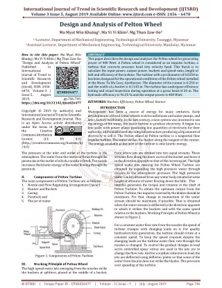
Design Analysis of Parts of Pelton Wheel Turbine. P M V Subbarao Professor Mechanical Engineering Department. Selection of right parts and right geometry to execute Pure Impulse…. HEPP with Pelton Wheel. Parts of Pelton Turbine. The main components of a Pelton turbine are:

E N D
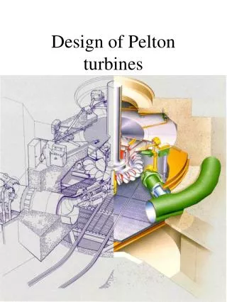
Design Analysis of Parts of Pelton Wheel Turbine P M V Subbarao Professor Mechanical Engineering Department Selection of right parts and right geometry to execute Pure Impulse…..
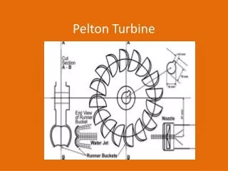
Parts of Pelton Turbine • The main components of a Pelton turbine are: • (i) water distributor and casing, • (ii) nozzle and deflector with their operating mechanism, • (iii) runner with buckets, • (iv) shaft with bearing, • (v) auxiliary nozzle. • Auxiliary nozzle is used as brake for reducing the speed during shut down. • The runner is located above maximum tail water to permit operation at atmospheric pressure.
Runner with Buckets The runner consists of a circular disc with a number (usually more than 15) of buckets evenly spaced around its periphery. Each bucket is divided vertically into two parts by a splitter that has a sharp edge at the centre and the buckets look like a double hemispherical cup. The striking jet of water is divided into two parts by the splitter.
A notch made near the edge of the outer rim of each bucket is carefully sharpened to ensure a loss-free entry of the jet into the buckets, i.e., the path of the jet is not obstructed by the incoming buckets.
Bucket Displacement Diagram Design of Nozzle is of Prime importance in Pelton Wheel
The Nozzle and Jet : A Key Step in Design b a d0 djet,VC Velocity of the jet at VC:
Jet carrying a discharge of Q to deliver a power P To generate a discharge of Q, we need a least jet diameter of
Diameter of the Jet at the outlet, do It is important to find out the VC and outlet jet diameters/areas
CFD Analysis of Free Jets & Flows In Air P M V Subbarao Professor Mechanical Engineering Department A Consultancy Project Sponsored By BHEL, Bhopal
The set of governing equations solved were primarily the continuity and the momentum equations. • These basic equations in Cartesian coordinate system for incompressible flows are given below, m Turbulent Viscosity
Industrial Correlations for Jet Area Optimal value of Outlet jet area, ao s is the displacement of spear
Pelton Wheel Distributor - CFD Analysis • The distributor to the Pelton wheel for the given geometry has been simulated using Fluent in a 3-d viscous incompressible flow simulation. • The set of governing equations solved were primarily the continuity and the momentum equations. • The given geometry was meshed using the unstructured tetrahedral meshes due to geometrical complexity. • An optimized tetrahedral mesh size of 25 was employed resulting in a a total of 62583 tetrahedral elements.
Mean Diameter of Pelton Runner Mean diameter or Pitch circle diameter: Dwheel Circumferential velocity of the wheel, Uwheel
Experimental values of Wheel diameter to jet diameter P in hp, H in meters and N in rpm
For maximum efficiency, the ratio should be from 11 to 14. The highest ratio used in the world is 110 (Kt. Glauraus Power House in Switzerland). Specifications of this Pelton wheel are: Power 3000HP (2.24MW) Speed: 500 rpm Dwheel= 5.36m djet,VC=48.77mm Head =1,650 m
Path Lines of Jet Dpelton Dwheel Vj,O dO
Number of buckets • The number of buckets for a given runner must be determined so that no water particle is lost. • Minimize the risks of detrimental interactions between the out flowing water particles and the adjacent buckets. • The runner pitch is determined by the paths of; • the bucket tip (diameter Dpelton), the Wheel diameter (DWheel). • and the relative paths of the water particles stemming from the upper and lower generators of the jet. • The bucket pitch must be selected so that no particle stemming from the lower generator of the jet can escape the runner without encountering any bucket.
Reference Position Bucket Duty Cycle
Zones of Bucket Duty Cycle • i) Approach of the tip to the jet (θj < −40◦). • ii) Initial feeding process : (θj = −40◦...−10◦). • iii) Entire separation of the jet (θj = −10◦...0◦) • iv) Last stage of inflow (θj = 0◦...15◦) • v) Last stage of outflow (θj = 15◦...50◦). • vi) Series of droplets (θj = −50◦...∞).
Sequence of Jet Bucket Interactions Dq=50 Dq=250 Dq=350 Dq=150
Dq=450 Dq=550
Minimum Number of Buckets The axis of the jet falls on Pitch Circle d Rwheel w Rpelton 2j 1D Dj,O, Vj,O 1A 1C 1B
q y 1E Minimum Number of Buckets d Rwheel w RPelton 2j = q+y dj,O, Vj,O 1C 1B
Minimum Number of Buckets tj : Time taken bye the jet to travel lj tb: Time taken by first bucket to travel y d RWheel w RPelton q y dO, Vj,O lj
d RW w RP q y dO, Vj,O lj • tj = lj/Vjet,O • tb = y/w
For better working tj < tb The minimum allowable value of y
d RW w RP q y dO, Vj,O lj
Maximum allowable angle between two successive buckets Minimum number of buckets Dr Taygun has suggested an empirical relation for z
Bucket Power Distribution Total 2 1 3 5 4 P(qj)
Geometric Details of Bucket The hydraulic efficiency depends more on the main bucket dimensions (length (A), width (B) and depth (C)). The shape of the outer part of its rim or on the lateral surface curvature also has marginal effect on hydraulic efficiency.