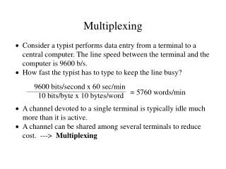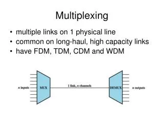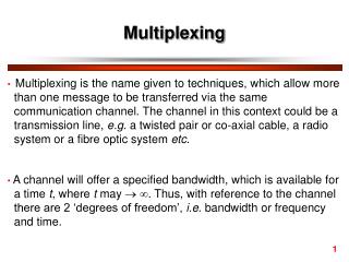
Multiplexing
Multiplexing. Lecture 4 Paul Flynn. Multiplexing. Frequency Division Multiplexing. FDM Useful bandwidth of medium exceeds required bandwidth of channel Each signal is modulated to a different carrier frequency Carrier frequencies separated so signals do not overlap (guard bands)

Multiplexing
E N D
Presentation Transcript
Multiplexing Lecture 4 Paul Flynn
Frequency Division Multiplexing • FDM • Useful bandwidth of medium exceeds required bandwidth of channel • Each signal is modulated to a different carrier frequency • Carrier frequencies separated so signals do not overlap (guard bands) • e.g. broadcast radio • Channel allocated even if no data
Analog Carrier Systems • AT&T (USA) • Hierarchy of FDM schemes • Group • 12 voice channels (4kHz each) = 48kHz • Range 60kHz to 108kHz • Supergroup • 60 channel • FDM of 5 group signals on carriers between 420kHz and 612 kHz • Mastergroup • 10 supergroups
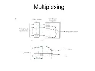
Synchronous Time Division Multiplexing • Data rate of medium exceeds data rate of digital signal to be transmitted • Multiple digital signals interleaved in time • May be at bit level of blocks • Time slots preassigned to sources and fixed • Time slots allocated even if no data • Time slots do not have to be evenly distributed amongst sources
TDM Link Control • No headers and tailers • Data link control protocols not needed • Flow control • Data rate of multiplexed line is fixed • If one channel receiver can not receive data, the others must carry on • The corresponding source must be quenched • This leaves empty slots • Error control • Errors are detected and handled by individual channel systems
Digital Carrier Systems • Hierarchy of TDM • USA/Canada/Japan use one system • ITU-T use a similar (but different) system • US system based on DS-1 format • Multiplexes 24 channels • Each frame has 8 bits per channel plus one framing bit • 193 bits per frame
Digital Carrier Systems (2) • For voice each channel contains one word of digitized data (PCM, 8000 samples per sec) • Data rate 8000x8X32 = 2048Kbps or 2.048Mbps • Five out of six frames have 8 bit PCM samples • Sixth frame is 7 bit PCM word plus signaling bit • Signaling bits form stream for each channel containing control and routing info • Same format for digital data • 30 channels of data • 7 bits per frame plus indicator bit for data or systems control • 31st channel is sync, • 16th channel is frame allignment
Plesiochronous Digital Hierarchy (PDH) • Bandwidth is incremented in blocks (Mbps) • 2 – 8 • 8 – 34 • 34- 140 • 140 – 565 • Problem arises with extraction of lower bandwidth links
Sonet/SDH • Synchronous Optical Network (ANSI) • Synchronous Digital Hierarchy (ITU-T) • Compatible • Signal Hierarchy • Synchronous Transport Signal level 1 (STS-1) or Optical Carrier level 1 (OC-1) • 51.84Mbps • Carry DS-3 or group of lower rate signals (DS1 DS1C DS2) plus ITU-T rates (e.g. 2.048Mbps) • Multiple STS-1 combined into STS-N signal • ITU-T lowest rate is 155.52Mbps (STM-1)
Statistical TDM • In Synchronous TDM many slots are wasted • Statistical TDM allocates time slots dynamically based on demand • Multiplexer scans input lines and collects data until frame full • Data rate on line lower than aggregate rates of input lines
Performance • Output data rate less than aggregate input rates • May cause problems during peak periods • Buffer inputs • Keep buffer size to minimum to reduce delay