Download
1 / 23
260 likes | 887 Vues
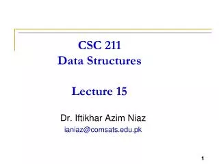
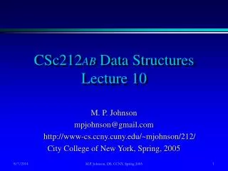
530.418 Aerospace Structures and Materials Lecture 1: Intro and Terms. Lockheed-Martin X-35 Joint Strike Fighter (JSF) The U.S. Department of Defense awarded Lockheed-Martin Corp. a contract that could be worth upwards of $200 billion to build its new radar-evading Joint Strike Fighter.

E N D
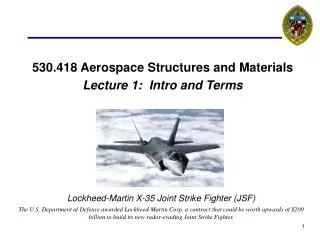
530.418 Aerospace Structures and MaterialsLecture 1: Intro and Terms Lockheed-Martin X-35 Joint Strike Fighter (JSF) The U.S. Department of Defense awarded Lockheed-Martin Corp. a contract that could be worth upwards of $200 billion to build its new radar-evading Joint Strike Fighter.
Kevin Hemker Professor of Mechanical Eng, Materials Science & Eng, Earth & Planetary Sciences, Johns Hopkins University Email: hemker@jhu.edu Tel. 410 516-4489 Tom Dragone Senior Principal Engineer, Material Scientist, Orbital Sciences Corp. Adjunct Associate Professor, Johns Hopkins University Email. Dragone.Tom@orbital.com Tel. 703 406-5413 The Hopkins – Orbital connection 530.418 Aerospace Structures
Importance of ethics The strength of the university depends on academic and personal integrity. In this course, you must be honest and truthful. Ethical violations include cheating on exams, plagiarism, reuse of assignments, improper use of the Internet and electronic devices, unauthorized collaboration, alteration of graded assignments, forgery and falsification, lying, facilitating academic dishonesty, and unfair competition. In addition, the specific ethics guidelines for this course are: • Students may collaborate in “figuring out” how to do homeworks but must calculate, create Excel spreadsheets, and write up solutions themselves. • Students may use old mid-term and final exams to review (examples will be posted on the course website) but not in the completion of current exams. • Students may not collaborate in any way in the process of completing exams. Report any violations you witness to the instructor. You may consult the associate dean of student affairs and/or the chairman of the Ethics Board beforehand. See the guide on “Academic Ethics for Undergraduates” and the Ethics Board Web site (http://ethics.jhu.edu) for more information.
Course mechanics • The distance classroom • All classes will be broadcast both ways. • We want as ‘live’ an experience as possible so please ask questions. We will have to negotiate the camera switching. • Hopkins students use the microphones on the desk. • Coversheet (e.g. rules and regulations) for course • See www.me.jhu.edu/~hemker/aero/index.htm • Course Outline • See www.me.jhu.edu/~hemker/aero/index.htm
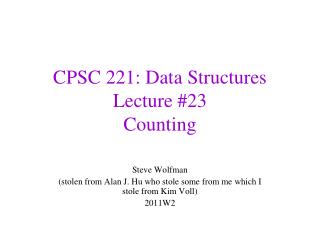
If not – change size and repeat !! Major parts of aerospace structural design • Analysis • Given: external loads + geometry(defined by aerodynamics + environments groups) • Devise: a structural arrangement to support these loads • Calc: internal loads/stresses on each part of the structure • Using: analytical methods (provides rough approx and feel) -or- finite elements (provides detailed analysis but little feel). • Assessment Are loads acceptable for given: • Material - Environment • Geometry - Time / # of cycles • Type of failure
Fracture Toughness Crack Size Fatigue Crack Initiation Crack Growth Metal Yield Rupture Composite FPF LPF Stability Buckling Crippling JOINT LOADS Weld , Braze Bond, Bolt Structure Design / Analysis Process GLOBAL LOADS Aerodynamics Inertial Applied GEOMETRY Planform Skin Construction Spar/Rib Layout MATERIALS Metal Composite SIZING Thickness Ply Orientation SHEAR-MOMENT DIAGRAM Section Loads Structure Idealization Stiffness Lamination Theory BOX BEAM ANALYSIS Component Loads (Cap Forces, Shear Flow) FAILURE ANALYSIS MS>0? Done Yes No
Aerospace nomenclature • Group 1: • Pitch, yaw, roll, primary structure, secondary structure, fuselage, wing, empennage, horizontal stabilizer, vertical stabilizer • Group 2: • Dihedral, flap, aileron, elevator, rudder, elevon, ruddervator, flaperon, canard • Group 3: • Span, chord, leading edge, trailing edge, wing root, wing tip, MAC, fuselage station, wing station, WBL • Group 4: • Wing box, Wing carry through, Main landing gear, nose landing gear, spar, spar cap, rib,longeron, frame, skin • Group 5: • Stringers, radome, engine pylon, engine nacelle, spoilers, fairing, loft, OML
Group 1 • Pitch • Motion within the vertical flight plane • Yaw • Motion perpendicular to the vertical flight plane • Roll • Motion about the aircraft primary axis • Primary Structure • Structure in the primary load path – failure could result in a loss of the aircraft • Secondary Structure • Structure not in the primary load path – failure does not lead to aircraft loss
Group 1 • Fuselage • Primary usable volume of aircraft • Wing • Primary aerodynamic lifting surface of aircraft • Empennage • Aft structure consisting of horizontal and vertical stabilizers • Horizontal Stabilizer • Aft lifting surface that trims aircraft pitching moment • Vertical Stabilizer (Tail) • Aft aero surface that provides lateral stability
Group 2 • Dihedral • Angle of wing from horizontal to provide roll stability • Flap • Wing trailing edge device increases lift for takeoff/landing • Aileron • Aero control surface on wing trailing edge that provides roll control • Elevator • Aero control surface on horizontal stabilizer that provides pitch control • Rudder • Aero control surface on vertical stabilizer that provides yaw control
Group 2 • Elevon • Aero control surface that combines elevator and aileron functions • Ruddervator • Aero control surface that combines rudder and elevator functions • Flaperon • Aero control surface that combines flap and aileron functions • Canard • Aft lifting surface that trims aircraft pitching moment
Group 3 • Span • Dimension along the length of the wing • Chord • Dimension on the wing along the flow path • Leading Edge • Forward edge of the wing • Trailing Edge • Aft edge of the wing • Wing Root • Intersection between the wing and the fuselage
Group 3 • Wing Tip • Outboard edge of wing • MAC • Mean aerodynamic chord – average of leading and trailing edges • Fuselage Station • Coordinate along the A/C axis centered forward of the nose and positive aft • Wing Station • Coordinate along the wing MAC from the root to the tip • WBL • Wing Butt Line – alternate phrase for wing station
Group 4 • Wing Box • Box beam structure that resists wing bending, shear and torsion loads • Wing Carry Through • Portion of wing box structure that carries load across fuselage • Main Landing Gear • Large landing gear that carry most of the aircraft weight on landing • Nose Landing Gear • Smaller landing gear that resist nose-slap down loads • Spar • Wing reinforcing structure that runs spanwise and resists wing bending
Group 4 • Spar Cap • Concentrated mass at wing spar-skin intersection to carry bending loads • Rib • Wing reinforcing structure that runs chordwise and resists crushing loads • Longeron • Fuselage reinforcing structure to carry bending loads • Frame • Fuselage reinforcing structure to resist fuselage buckling • Skin • Thin shell structure of fuselage and wing that primarily resists shear load
Group 5 • Stringers • Beams attached to skins that provide buckling stability and support bending • Radome • Shell structure at aircraft nose, often housing some sort of antenna • Engine Pylon • Structure to support wing mounted engines • Engine Nacelle • Structure to provide aerodynamic contouring of wing mounted engines • Spoilers • Upward deflection wing surfaces that reduce lift after landing
Group 5 • Fairing • Non-load-bearing structure to provide aerodynamic contouring between surfaces • Loft • Outer shape of the aircraft driven by aerodynamic requirements • OML • Outer Mold Line – alternate phrase for loft
Review: building the Wright flier http://magma.nationalgeographic.com/ngm/0312/feature1/flyer/main.html