Download
1 / 1
20 likes | 238 Vues
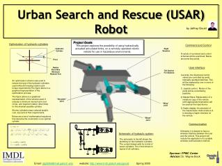
Urban Search and Rescue (USAR) Robot. by Jeffrey Gould. Project Goals This project explores the possibility of using hydraulically actuated articulated limbs, on a remotely operated robotic vehicle for use in hazardous environments. Optimization of hydraulic cylinders. Command and Control.

E N D
Urban Search and Rescue (USAR) Robot by Jeffrey Gould Project Goals This project explores the possibility of using hydraulically actuated articulated limbs, on a remotely operated robotic vehicle for use in hazardous environments. Optimization of hydraulic cylinders Command and Control Hydraulic Cylinder Rigid Skeleton A variety of command and control schemes will be examined. Below are some key points. Pivot Radius Describes Minimum Moment Arm User interface Tail Section For Balance • Currently, the directional control valves are controlled by small, manually operated switches. This will be replaced by one or more of the following: • Joystick control. Motion of the joints will be controlled by joysticks. • Master/Slave. Manipulation of a miniature copy of the vehicle (with appropriate kinematics) will be used as the input device. • Haptic display. An extension of the master/slave method above is to develop a haptic interface for the vehicle. An optimization scheme was used to reduce the size of the hydraulic cylinders used while still meeting rotation and torque requirements.The figure above is a graphical representation of the optimization process. The figure above is a graphical representation of the scheme used. It ensures a minimum moment arm (red circle), and required rotation (blue lines) for the shortest possible cylinder. Shorter cylinders mean reduced weight, cost, size and oil flow requirements. Below are a set of mathematical equations that describe the constraints on an optimal cylinder. “Shoulder” Joint “Wing” Joint “Elbow” Joint Communication Ultimately it is desired to have a wireless interface between the user and the vehicle. This project will include the application of a suitable wireless communication method. Schematic of hydraulic system The schematic to the left shows the plumbing for two hydraulic cylinders. The current design calls for a total of seven cylinders. The circuit shown is typical of all cylinders. Sponsor: FPMC Center Advisor: Dr. Wayne Book Email: gtg329d@mail.gatech.edu website: http://www.imdl.gatech.edu/jgould Spring 2003