Download
1 / 5
50 likes | 74 Vues
This document outlines the hardware requirements for the XFEL C+C system to receive, process, and store timing signals, distribute fast lines, synchronize with external sources, and provide diagnostic indications.

E N D
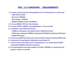
XFEL C+C HARDWARE : REQUIREMENTS 1) To receive, process and store Timing Signals from TR ( Timing Receiver ) in same crate : - 5 MHz Bunch CLOCK - Bunch train TRIGGER - Event Number = TRAIN ID - BUNCH PATTERN or Bunch PATTERN ID 2) To receive BUNCH VETO from Veto Hardware 3) To receive STATUS / ERROR ( and possibly Busy ?? ) from each FEE 4) To distribute to each FEE three fast lines : - 100 MHz un-interrupted clock, phase-locked to 5 MHz Bunch Clock - START pulse, followed by TRAIN ID, followed by PATTERN ID, followed by STOP signal - BUNCH VETO signal 5) To process any BUSY information from crate controller to stop the following START pulse 6) To generate all Timing Signals in Stand-Alone mode without TR 7) To synchronise to other light sources’ Timing Systems, i.e. to accept external CLOCK and possibly TRIGGER at different frequencies 8) To provide diagnostic and visual indication of CLOCK, TRIGGER, etc. performance and presence / absence of any FEE
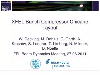
t1 T2 T1+T2 INPUTS AND OUTPUTS – TIMING RELATIONSHIP 5 MHz clock in D1 TRIGGER in VETO in 100 MHz clock out T1 TRIGGER out D2 VETO out
XFEL C+C HARDWARE : MORE INFORMATION / QUESTIONS -1- 1) TRIGGER “Telegram” from TR : - same line / different lines for TRIGGER, Train ID, Bunch Pattern ?? - Bunch Pattern or Pattern ID ? ( Pattern ID look-up table on C+C ?? ) 2) FEE feedback line : Status only ( e.g.. Normally floating high, pulled low by FEE when powered ), or will contain information ( e.g.. go high when ‘busy’ or ‘error’ ) ?? 3) External clock input at other test sites : - 20 MHz range ?? - Always use internal 100 MHz clock or PLL to different clock ?? 4) Bunch Veto signal – how fast / latency ?? 5) Calibration Pattern ?? ( pre-loaded into a memory on C+C ?? ) 6) Veto Disable Pattern ?? 7) 100 MHz clock output : - max. jitter ?? - programmable delay / step size ?? 8) Output Clock / Start/Stop pulses phase relationship : - only adjustable on C+C Master, i.e. same for all FEEs ?? - same cable length for all FEEs ?? - or individual delay adjustments on each C+C FanOut => more complex FanOuts ??
XFEL C+C HARDWARE : MORE INFORMATION / QUESTIONS -2- 9) Connection between C+C Master and FanOuts : - on custom backplane all signals / FEE feedbacks only ?? - use single or double FanOut layer ?? 10) C+C FanOut cards : - separate power on backplane => not TCA-intelligent cards ?? - separate ‘dumb’ FanOut cards and crate ?? - on / near detector => fewer cables ?? 11) LVDS connectors : - RJ45 – bulky, 4-pairs only, but can use 2x LEDs - Double-stack RJ45 – availability / height ?? - HDMI - size / more signal pairs / more grounds/shielding ?? - Double stack HDMI - size ?? - mini-HDMI ?? 12) Is there any C&C System interface to MPS ( Machine Protection System ) ??