EMC Testing for Emission and Immunity
450 likes | 730 Vues
Diethard E. C. Moehr, I&S CTF EMC. EMC Testing for Emission and Immunity. Measurement procedure according to CISPR 16, Part 1 (VDE 0877 Part 1 and 2). Measurement procedure for conducted emission on power lines and on data and signal lines: VDE 0877, Part 1 (CISPR 16 - 1)

EMC Testing for Emission and Immunity
E N D
Presentation Transcript
Diethard E. C. Moehr, I&S CTF EMC EMC Testing for Emission and Immunity
Measurement procedure according to CISPR 16, Part 1 (VDE 0877 Part 1 and 2) • Measurement procedure for conducted emission on power lines and on data and signal lines: • VDE 0877, Part 1 (CISPR 16 - 1) • Measurement procedure for radiated emission: • electrical field • VDE 0877, Part 2 (CISPR 16 - 1)
Measuring Standards on EMC The measuring standards for emission are product related. This means that there are standards designated to special products or product groups. The measuring standards for immunity are phenomena related. This means that different immunity phenomena have to be tested independent of the product group. Emission Immunity
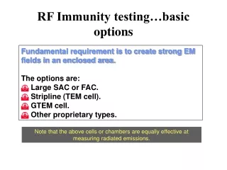
Measuring equipment needed for emission measurements • LISNs • Screened Rooms • Measuring receivers with Average and CISPR detectors • Auxiliary measuring equipment Conducted emission 10 kHz - 30 MHz Radiated emission 30 MHz - 1 GHz • OATS with field attenuation according to CISPR 16 and VDE 0877, Part 2 • Measuring receivers with Average and CISPR detectors • Auxiliary measuring equipment
Measuring procedure for radiated emission • Measuring distance: 10 meters • No ambient noise • OATS according to CISPR 16 and VDE 0877 Part 2 • EUT emission maximum has to be recorded • 360 ° turning of the turntable • Altitude variation of the receiving antenna 1 - 4 meter • Horizontal & vertical polarization • Install the EUT like in reality
OATS Receiving antenna EUT Measuring receiver Tripod & antenna mast Turntable Measuring procedure for radiated emission
Measuring procedure for conducted emission - Part 1 1 metal sheet 2 m x 2 m 2 EUT 3 bundled cable 4 LISN 5 shielded interconnection cable 6 measuring receiver B earthing point M connection to measuring receiver P connection EUT Measure in cm DIN VDE 0877, Part 1 Measuring set up for an EUT supplied by public mains
Measuring procedure for conducted emission - Part 2 DIN VDE 0877, Part 2 Measure in cm 1 metal sheet 2 m x 2 m 2 EUT 3 power supply cable 4 separate connection cable 5 LISN 6 touchable metal surface of the EUT A connection power supply B connection earthing point P connection EUT H connection artificial hand M connection measuring receiver D metal foils ground separate from power supply EUT with artificial hand
Measuring procedure for conducted emission - Part 3 Measure in cm DIN VDE 0877, Part 3 1 metal sheet 2 m x 2 m 2 EUT (Fax machine) 3 power supply 4 communication cable 5 V - LISN 6 - LISN 7 measuring receiver B earthing point M connection to measuring receiver P connection EUT Measuring set up for an EUT with different supply cables
Immunity phenomena ESD • Rubbing or heating up of non conductive materials • Triboelectric effect RFI • Radio & TV stations • Walkie talkies • Wireless communication • Mobile phones and others
Immunity phenomena BURST • All electrical switches • Contactors • Fluorescent lights and other gas discharge devices SURGE • Lighting • Switching of large Loads COND. IMMUNITY • Coupling of sinusoidal disturbances into cables
Measuring equipment neededfor immunity tests ESD ESD Simulator RFI Transmitting antennas, generators, power amplifiers,anechoic chambers, field sensors and other auxillary equipment BURST BURST simulator and coupling clamps and devices SURGE SURGE simulator and coupling clamps and devices CONDUCTED IMMUNITY Generators, coupling / decoupling networks (CDNs) For all immunity tests it is at least recommended to use shielded rooms.
Immunity test procedures ESD Electrostatic discharge
+ - The Triboelectric Effect • The reason for the discharge of static electricity is the Triboelectric Effect. • Non conductive material have the tendency to build up static electricity if they are rubbed against each other or if they are heated up. Air Artificial resin Glass Nylon Hair Silk Cotton Wood, Paper Amber Polyurethane Polyethylene Rubber PVC Silicon Teflon
Test impulse as per IEC 61000-4-2 Test impulse as per the old IEC 801-2 Test Waveforms in IEC Standards -- Time Waveforms
Frequency spectrum as per IEC 61000-4-2 Frequency spectrum as per IEC 801-2 Test Waveforms in IEC Standards -- Frequency Spectra
dischargeswitch dischargetip (vacuum relay) 10 pF 150 pF Circuit diagram of the ESD simulator
Shielded room DischargeResistor Wall of the shielded room ESD-Simulator N-Connector 50 R 50 cm SUHNERRG 214 U 2 R Earth cable Tektronix 11402 powersupply -20dB 50 R BNC BNCConnector Printer Measuring set up for verification of the ESD pulse (direct contact of the discharge tip)
Immunity test procedures RFI Immunity against radiated fields
anechoic chamber wooden table0,8 meters high area of uniform field power supply filter transmitting antenna internal cablelength < 1 meter feed throughs floor absorbers control room ferrite or filters for cable decoupling measuringinstruments feed throughs generatoramplifiers amplifier room Setup for radiated field testing
Immunity test procedures BURST Low energy fast transients
Low energy fast transients Part 1 Sources of Noise Coupling mechanism Receptors • Power switches vacuum relays,contactors, relaysand others • protective devices (fuses, gas discharges and others) • electrical motors with brushes like in vacuum cleaners, hair dryer and motors in industrial applications • Electrical and electronic devices of any kind • Power linesdata linessignal linescommunication lines Principle of source coupling receptors applied to low energy fast transients (BURST).
Low energy fast transients Part 2Test levels for BURST testing
Gas Discharge R C M D C D 50 Ohmcoaxial output C R R L S M R S U voltage source charging resistor charging capacitance pulse forming resistor matching resistor decoupling capacitance U C R S S Low energy fast transients Part 3Principle of the BURST generator
t/msec Pulse repetition rate 5 kHz V O Low energy fast transients Part 4BURST impulse package
50 nsec +/- 30 % 5 nsec +/- 30 % Low energy fast transients Part 5Single BURST pulse
Immunity test procedures SURGE High energy transients
L r R C R C C m R S1 - S2 U high voltage source charging resistor charging capacitance pulse forming resistor matching resistor inductance to adjust the rise time of the pulse SURGE testing Part 1 Circuit diagram of the generator (combinationwave generator)
Rise time: T = 1,67 x T = 1,2 µsec ± 30 % 1 Time of 50 % amplitude: T = 50 µsec ± 20 % 2 SURGE testing Part 2 Pulse shape of open circuit voltage according to IEC 60060-1
Rise time: T = 1,25 x T = 8 µsec ± 20 % 1 Time of 50 % amplitude: T = 20 µsec ± 20 % 2 SURGE testing Part 3 Pulse shape of the short circuit current according to IEC 60060-1
Rise time: T = 1,67 x T = 10 µsec ± 30 % 1 Time of 50 % amplitude: T = 700 µsec ± 20 % 2 SURGE testing Part 4 Pulse shape of the open circuit voltage according to CCITT
SURGE testing Part 5 Coupling network for SURGE pulses for a. c. and d. c. mains
SURGE testing Part 6 Recommended test levels according to IEC 61000-4-5
Contact: Diethard Moehr I&S CTF EMC Schuhstraße 60 D-91052 Erlangen Phone:+49 (9131) 7-27210Mail:diethard.moehr@siemens.com Thank you very much for your attention.