Download

1 / 24
260 likes | 568 Vues
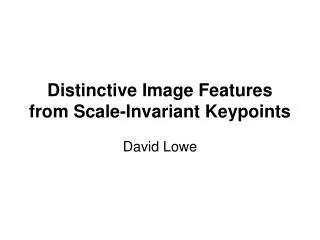
Distinctive Image Features from Scale-Invariant Keypoints David Lowe. Presented by Tony X. Han March 11, 2008. SIFT: Scale Invariant Feature Transform (The outline of the computation procedure). Why SIFT?.

E N D
Distinctive Image Featuresfrom Scale-Invariant KeypointsDavid Lowe Presented by Tony X. Han March 11, 2008
SIFT: Scale Invariant Feature Transform (The outline of the computation procedure)
Why SIFT? • The keypoint descriptors are highly distinctive, which allows a single feature to find its correct match with good probability in a large database of features. • The Harris corner detector is very sensitive to changes in image scale, so it does not provide a good basis for matching images of different sizes. • While SIFT is not fully affine invariant, a special approach is used in which the local descriptor allows relative feature positions to shift significantly with only small changes in the descriptor. (This is basically just a hack)
Step 1: Detection of scale-space extrema • It has been shown by Koenderink (1984) and Lindeberg (1994) that under a variety of reasonable assumptions the only possible scale-space kernel is the Gaussian function. Therefore, the scale space of an image is defined as a function, L(x; y;\sigma ), that is produced from the convolution of a variable-scale Gaussian, G(x; y;\sigma ), with an input image, I(x; y):
Step 1: Detection of scale-space extrema (Cont.) • To efficiently detect stable keypoint locations in scale space, Lowe proposed using scale-space extrema in the difference-of-Gaussian function convolved with the image, D(x; y; \sgima ), which can be computed from the difference of two nearby scales separated by a constant multiplicative factor k: • The initial image is incrementally convolved with Gaussians to produce images separated by a constant factor k in scale space, shown stacked in the left column.
Step 1: Detection of scale-space extrema (Cont.) • In order to detect the local maxima and minima of D(x; y; ), each sample point is compared to its eight neighbors in the current image and nine neighbors in the scale above and below It is selected only if it is larger than all of these neighbors or smaller than all of them. The cost of this check is reasonably low due to the fact that most sample points will be eliminated following the first few checks. Maxima and minima of the difference-of-Gaussian images are detected by comparing a pixel (marked with X) to its 26 neighbors in 3x3 regions at the current and adjacent scales (marked with circles).
Step 1: Detection of scale-space extrema (Cont.) It might seem surprising that the repeatability does not continue to improve as more scales are sampled. The reason is that this results in many more local extrema being detected, but these extrema are on average less stable and therefore are less likely to be detected in the transformed image.
Step 2: Accurate keypoint localization • Once a keypoint candidate has been found by comparing a pixel to its neighbors, the next step is to perform a detailed fit to the nearby data for location, scale, and ratio of principal curvatures. This information allows points to be rejected that have low contrast (and are therefore sensitive to noise) or are poorly localized along an edge. • His approach uses the Taylor expansion (up to the quadratic terms) of the scale-space function, D(x; y; \sigma), shifted so that the origin is at the sample point:
Step 2: Accurate keypoint localization (Cont.) If the offset \hat{x} is larger than 0.5 in any dimension, then it means that the extremum lies closer to a different sample point. In this case, the sample point is changed and the interpolation performed instead about that point. The final offset \hat{x} is added to the location of its sample point to get the interpolated estimate for the location of the extremum.
Step 2: Accurate keypoint localization (Cont.) • Eliminating edge responses: A poorly defined peak in the difference-of-Gaussian function will have a large principal curvature across the edge but a small one in the perpendicular direction. The principal curvatures can be computed from a 2x2 Hessian matrix, H, computed at the location and scale of the keypoint:
Step 2: Accurate keypoint localization (Cont.) The eigenvalues of H are proportional to the principal curvatures of D. we can avoid explicitly computing the eigenvalues, as we are only concerned with their ratio. Let \alpha be the eigenvalue with the largest magnitude and \beta be the smaller one. Then, we can compute the sum of the eigenvalues from the trace of H and their product from the determinant:
Step 3: Orientation assignment • An orientation histogram is formed from the gradient orientations of sample points within a region around the keypoint. The orientation histogram has 36 bins covering the 360 degree range of orientations. Each sample added to the histogram is weighted by its gradient magnitude and by a Gaussian-weighted circular window with a \sigma that is 1.5 times that of the scale of the keypoint. • Peaks in the orientation histogram correspond to dominant directions of local gradients. The highest peak in the histogram is detected, and then any other local peak that is within 80% of the highest peak is used to also create a keypoint with that orientation. Therefore, for locations with multiple peaks of similar magnitude, there will be multiple keypoints created at the same location and scale but different orientations. Only about 15% of points are assigned multiple orientations, but these contribute significantly to the stability of matching. Finally, a parabola is fit to the 3 histogram values closest to each peak to interpolate the peak positionfor better accuracy.
Step 4: The local image descriptor First the image gradient magnitudes and orientations are sampled around the keypoint location, using the scale of the keypoint to select the level of Gaussian blur for the image. In order to achieve orientation invariance, the coordinates of the descriptor and the gradient orientations are rotated relative to the keypoint orientation.
Step 4: The local image descriptor(Cont.) • It is important to avoid all boundary affects in which the descriptor abruptly changes as a sample shifts smoothly from being within one histogram to another or from one orientation to another. Therefore, trilinear interpolation is used to distribute the value of each gradient sample into adjacent histogram bins. In other words, each entry into a bin is multiplied by a weight of 1-d for each dimension, where d is the distance of the sample from the central value of the bin as measured in units of the histogram bin spacing. (To achieve certain affine invariant)
Step 4: The local image descriptor(Cont.) • Finally, the feature vector is modified to reduce the effects of illumination change. First, the vector is normalized to unit length. A change in image contrast in which each pixel value is multiplied by a constant will multiply gradients by the same constant, so this contrast change will be canceled by vector normalization. • However, non-linear illumination changes can also occur due to camera saturation or due to illumination changes that affect 3D surfaces with differing orientations by different amounts. These effects can cause a large change in relative magnitudes for some gradients, but are less likely to affect the gradient orientations. Therefore, we reduce the influence of large gradient magnitudes by thresholding the values in the unit feature vector to each be no larger than 0.2, and then renormalizing to unit length.
Application to object recognition • Keypoint matching • Efficient nearest neighbor indexing • Clustering with the Hough transform • Solution for affine parameters(i.e. Constrain again by affine warping)
Results: • All steps of the recognition process can be implemented efficiently, so the total time to recognize all objects in Figures 12 or 13 is less than 0.3 seconds on a 2GHz Pentium 4 processor. We have implemented these algorithms on a laptop computer with attached video camera, and have tested them extensively over a wide range of conditions. In general, textured planar surfaces can be identified reliably over a rotation in depth of up to 50 degrees in any direction and under almost any illumination conditions that provide sufficient light and do not produce excessive glare. For 3D objects, the range of rotation in depth for reliable recognition is only about 30 degrees in any direction and illumination change is more disruptive. For these reasons, 3D object recognition is best performed by integrating features from multiple views, such as with local feature view clustering (Lowe, 2001).