
SYSTEM ARCHITECTURE
E N D
Presentation Transcript
Control system architecture can range from simple local control to highly redundant distributed control. SCADA systems, by definition, apply to facilities that are large enough that a central control system is necessary. Reliability criteria for C4ISR facilities dictate the application of redundant or distributed central control systems.
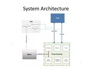
Local control Figure 3-1 describes a system architecture in which sensors, controller, and controlled equipment are within close proximity and the scope of each controller is limited to a specific system or subsystem. Local controllers are typically capable of accepting inputs from a supervisory controller to initiate or terminate locally-controlled automatic sequences, or to adjust control set points, but the control action itself is determined in the local controller. Required operator interfaces and displays are also local. This provides a significant advantage for an operator troubleshooting a problem with the system, but requires the operator to move around the facility to monitor systems or respond to system contingencies. Examples of local control are the packaged control panels furnished with chillers or skid-mounted pump packages.
Centralized control Centralized control describes a system in which all sensors, actuators, and other equipment within the facility are connected to a single controller or group of controllers located in a common control room. Locating all controls, operator interfaces and indicators in a single control room improves operator knowledge of system conditions and speeds response to contingencies. This type of system architecture was common for power plants and other facilities using single-loop controllers or early digital controls in the past, but it has now been largely supplanted by distributed control because of the high cost associated with routing and installing all control system wiring to a central location. Centralized control systems should only be considered for small C4ISR facilities and if used, must have fully redundant processors. Where redundancy is provided in a centralized control system segregated wiring pathways must be provided to assure that control signals to and from equipment or systems that are redundant are not subject to common failure from electrical fault, physical or environmental threats (figure 3-2).
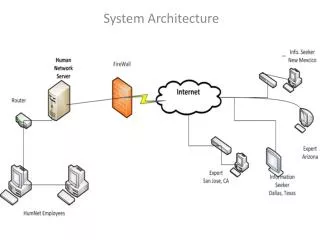
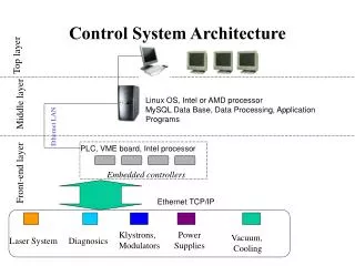
Distributed control Distributed control system architecture (figure 3-3) offers the best features of both local control and centralized control. In a distributed control system, controllers are provided locally to systems or groups of equipment, but networked to one or more operator stations in a central location through a digital communication circuit. Control action for each system or subsystem takes place in the local controller, but the central operator station has complete visibility of the status of all systems and the input and output data in each controller, as well as the ability to intervene in the control logic of the local controllers if necessary
There are a number of characteristics of distributed control architecture which enhance reliability: • (1) Input and output wiring runs are short and less vulnerable to physical disruption or electromagnetic • Interference • (2) A catastrophic environmental failure in one area of the facility will not affect controllers or wiring • located in another area. • (3) Each local controller can function on its own upon loss of communication with the central controller. • b. There are also specific threats introduced by distributed control architecture that must be addressed in the design of the system: • Networks used for communication may become electronically compromised from outside the facility. • (2) Interconnection of controllers in different locations can produce ground loop and surge voltage problems.
(3) If the central controller is provided with the ability to directly drive the output of local controllers for purposes of operator intervention, software glitches in the central controller have the potential to affect multiple local controllers, compromising system redundancy. (4) Distributed control system architecture redundancy must mirror the redundancy designed into the mechanical and electrical systems of the facility. Where redundant mechanical or electrical systems are provided, they should be provided with dedicated controllers, such that failure of a single controller cannot affect more than one system. Equipment or systems that are common to multiple redundant subsystems or pathways, (such as generator paralleling switchgear) should be provided with redundant controllers.
Types of distributed control systems a. Plant distributed control system (DCS): While the term DCS applies in general to any system in which controllers are distributed rather than centralized, in the power generation and petrochemical process industries it has come to refer to a specific type of control system able to execute complex analog process control algorithms at high speed, as well as provide routine monitoring, reporting and data logging functions. In most applications, the input and output modules of the system are distributed throughout the facility, but the control processors themselves are centrally located in proximity to the control room. These systems typically use proprietary hardware, software and communication protocols, requiring that both replacement parts and technical support be obtained from the original vendor b. Direct digital control (DDC): DDC systems are used in the commercial building heating, ventilation and air conditioning (HVAC) industry to monitor and maintain environmental conditions. They consist of local controllers connected to a network with a personal computer (PC) based central station which provides monitoring, reporting, data storage and programming capabilities. The controllers are optimized for economical HVAC system control, which generally does not require fast execution speeds. Their hardware and control software are proprietary, with either proprietary or open protocols used for network communication
c. Remote terminal unit (RTU) based SCADA: RTU-based systems are common in the electric, gas and water distribution industries where monitoring and control must take place across large geographical distances.The RTUs were developed primarily to provide monitoring and control capability at unattended sites such as substations, metering stations, pump stations, and water towers. They communicate with a central station over telephone lines, fiber-optics, radio or microwave transmission. Monitored sites tend to be relatively small, with the RTU typically used mainly for monitoring and only limited control. Hardware and software are proprietary, with either proprietary or open protocols used for data transmission to the central station. d. Programmable logic controller (PLC) based systems: PLCs, which are described in greater detail in the next section, can be networked together to share data as well as provide centralized monitoring and control capability. Control systems consisting of networked PLCs are supplanting both the plant DCS and the RTU-based systems in many industries. They were developed for factory automation and have traditionally excelled at high speed discrete control, but have now been provided with analog control capability as well. Hardware for these systems is proprietary, but both control software and network communication protocols are open, allowing system configuration, programming and technical support for a particular manufacturer’s equipment to be obtained from many sources.
Programmable logic controllers The recommended controller for SCADA systems is the programmable logic controller (PLC). PLCs are general-purpose microprocessor based controllers that provide logic, timing, counting, and analog control with network communications capability. a. PLCs are recommended for the following reasons: • They were developed for the factory floor and have demonstrated high reliability and tolerance for heat, vibration, and electromagnetic interference. • Their widespread market penetration means that parts are readily available and programming and technical support services are available from a large number of control system integrators • They provide high speed processing, which is important in generator and switchgear control applications. • They support hot standby and triple-redundant configurations for high reliability applications
b. A PLC consists of the required quantities of the following types of modules or cards, mounted on a common physical support and electrical interconnection structure known as a rack. A typical PLC rack configuration is shown in figure 3-4. (1) Power supply: The power supply converts facility electrical distribution voltage, such as 120 VAC or 125 VDC to signal level voltage used by the processor and other modules. (2) Processor: The processor module contains the microprocessor that performs control functions and computations, as well as the memory required to store the program. (3) Input/Output (I/O): These modules provide the means of connecting the processor to the field devices. (4) Communications: Communications modules are available for a wide range of industry-standard communication network connections. These allow digital data transfer between PLCs and to other systems within the facility. Some PLCs have communications capability built-in to the processor, rather than using separate modules (5) Communication Media and Protocols: The most common communication media used are copper-wire, coaxial, fiber-optics, and wireless. The most common “open” communication protocols areEthernet, Ethernet/IP, and DeviceNet. “Open” systems generally provide “plug and play” features in which the system software automatically recognizes and communicates to any compatible device that is connected to it. Other widely accepted open protocols are Modbus, Profibus, and ControlNet.
(6) Redundancy: Many PLCs are capable of being configured for redundant operation in which one processor backs up another. This arrangement often requires the addition of a redundancy module, which provides status confirmation and control assertion between the processors. In addition, signal wiring to redundant racks is an option
c. All software and programming required for the PLC to operate as a standalone controller is maintained on-board in the processor. PLCs are programmed with one of the following standard programming languages: • Ladder Diagrams: Used primarily for logic (Boolean) operations and is easily understood by electricians and control technicians. This is the most commonly used language in the United States and is supported by all PLC suppliers. • Function Block Diagrams: Used primarily for intensive analog control (PID) operations and is available only in “high-end” PLC’s. It is more commonly used outside the United States. • Sequential Function Chart: Used primarily for batch control operations and is available only in high-end” PLC’s. • Structured Text: Used primarily by PLC programmers with a computer language background and is supported only in “high-end” PLC’s.
d. SCADA PLCs should be specified to be programmed using ladder diagrams. This language is very common, and duplicates in format traditional electrical schematics, making it largely understandable by electricians and technicians without specific PLC training. The ladder logic functions the same as equivalent hard-wired relays. The PLCs in a SCADA system will be networked to one or more central personal computer (PC) workstations, which provide the normal means of human machine interface (HMI) to the system. These PCs will be provided with Windows-based HMI software that provides a graphical user interface (GUI) to the control system in which information is presented to the operator on graphic screens that are custom-configured to match the facility systems. For example, the electrical system status may be shown on a one-line diagram graphic in which open circuit breakers are colored green, closed breakers are colored red, and voltage and current values are displayed adjacent to each bus or circuit breaker
Redundant PLCs Where redundant PLC Systems are required, they may utilize a warm standby, hot standby, or voting configuration. Figure 3-5 shows a typical system configuration for redundant PLCs in either warm or hot standby. Both processors have continuous access to the I/O over redundant buses or networks, and register data and status information are exchanged over a dedicated fiber optic link. In warm standby configuration, the primary processor is running the program and controlling the output states. Upon failure of the primary processor, the standby processor takes over and begins to run the program. In a hot standby configuration, both processors are running continuously with their program scans synchronized over the fiber optic link. If one processor fails, the other takes control with a “bumpless” transfer in which the outputs do not change state. The hot standby configuration is recommended for most SCADA applications. For highly critical applications, a triple-redundant voting scheme, shown in figure 3-6, may be used. In this configuration three processors run continuously with synchronized scans, using either shared input data or independent input data from redundant sensors. The outputs of the processors pass through a two-out-of three (2oo3) voter to select the control value to the process. A spare voter prevents this from becoming an opportunity for a single point of failure
Safety PLCs A recommended means of assuring that PLC hardware and software meet specified reliability criteria is through specification of PLCs that are certified for use in Safety Instrumented Systems according to IEC 61508. This standard, while intended for application to protective systems used in manufacturing, chemical, and nuclear facilities, represents the only independently verified criteria for PLC reliability and diagnostic capability. PLCs meeting the requirements of this standard must have diagnostic coverage for failure of the power supply, processor and input and output modules. They must also have been shown toprovide a minimum reliability level defined in terms of probability of failure on demand (PFD), or probability of failure per hour (PFPH). Safety integrity level (SIL) target reliability indices for PLCs in lowdemand operation modes (such as controlling a standby power system) are given in table 3-1. For PLCs in continuous operation (such as controlling a base load power plant), the corresponding SIL levels are given in table 3-2. These values can be used in conjunction with the reliability analysis techniques to determine the required SIL for a specific application.
Table 3-1. Safety integrity levels – low demand operation Table 3-2. Safety integrity levels – continuous operation
Recommended configurations Three levels of SCADA system architecture are recommended to support C4ISR facilities. These vary in configuration to correspond to the size, criticality, and amount of mechanical and electrical equipment installed in the facility as noted. a. The small system is recommended to support a remote data and/or telephone switch site. Such a facility would generally include a single service transformer and a single standby diesel generator. Equipment inside would consist of a small rectifier for a 48 VDC bus, a small inverter, and two or more stand-alone direct-expansion cooling units. Systems for these facilities may not achieve the reliability/availability criteria specified for larger facilities. The level of SCADA system redundancy should reflect the mechanical/electrical system redundancy. See figure 3-7 for a suggested configuration
b. The medium system is recommended to support a main computer facility, which would include multiple service transformers and standby generators with paralleling switchgear, one or two large UPS systems, and multiple refrigeration machines with associated auxiliary equipment. SCADA systems for this size facility should utilize redundant distributed control architecture. The level of PLC redundancy should be selected based on the design of the mechanical and electrical systems. Two options and suggested SCADA configurations are provided
c. Figure 3-8 presents a suggested SCADA configuration applicable to a facility with mechanical and electrical systems designed to provide redundancy through segregated systems. In this case, PLCs controlling individual systems must have a reliability level adequate to maintain the required availability at the system they serve, but do not necessarily have to be redundant, as redundancy is provided through the N+X system approach. Failure of a single PLC will affect only the system it controls and the remaining systems continue to meet the mission-critical load.
d. Figure 3-9 presents a suggested SCADA configuration for a similarly sized facility in which mechanical and electrical systems utilize redundant components in a manifold configuration. In this design, any combination of components can be selected to serve the load. This provides greater flexibility than segregating components into redundant systems, but requires common control of all components, making the PLC a potential single point of failure. In this configuration, system-level PLCs must have redundancy adequate to meet the required availability of the system. e. A large system serving a multi-facility site consisting of several installations will require a central supervisory control room networked to distributed control within the individual buildings appropriate to the mission and reliability criteria of each facility. A control room will typically be located in each central power plant that is required for such a facility and the system can also be accessed from other locations distributed along the network. Redundant and segregated pathways are recommended for the on-site communication network. See figure 3-10 for a suggested configuration.